Recent Progress in Synthesis of Plate-like ZnO and its Applications: A Review
Article information
Abstract
Zinc oxide (ZnO) is one of the most versatile semiconductors, and one-dimensional (1D) ZnO nanostructures have attracted significant interest for use in ultraviolet (UV) lasers, photochemical sensors, and photocatalysts, among other applications. It is known that 1D ZnO nanowires can be fabricated readily owing to the anisotropic growth of ZnO along the [0001] direction. However, this type of growth results in a decrease in the surface area of the (0001) plane, which plays a vital role not only in UV lasing but also in the photocatalytic process. Thus, we attempted to synthesize ZnO crystals with an increased polar surface area by controlling the crystal growth process. The purpose of this review is to propose a simple route for the synthesis of plate-like ZnO crystals with highly enhanced polar surfaces and to explore their feasibility for use in UV lasers as well as as a photocatalyst and antibacterial agent. In addition, we highlight the recent progress made in the pilot-scale synthesis of plate-like ZnO crystals for industrial applications.
1. Introduction
Zinc oxide (ZnO) is used widely in various industrial fields, including in photocatalysis, optoelectronic devices, cosmetics, antibacterial agents, food supplement additives, animal feed, textiles, and pigments. In 2012, the annual global production of ZnO reached 33,400 tons.1,2) In 2001, Yang and coworkers demonstrated the selective crystal growth of ZnO nanorods on the gold-coated area of a sapphire (single-crystal Al2O3) substrate by the vapor-liquid-solid (VLS) crystal growth method while using gold as the catalyst.3) Based on this development, it has been suggested that the technological limitations of the top-down processes used for fabricating integrated circuits, which rely heavily on photolithography, can be overcome by using bottom-up processes instead. As a result, academic and industrial interest in ZnO as a semiconductor has increased significantly.
ZnO with a wurtzite structure has a direct wide bandgap of 3.37 eV and an exciton binding energy of 60 meV. Because this is higher than the thermal energy at room temperature (26 meV), polariton lasing can occur.4–6) In the early 2000 s, ZnO attracted considerable attention as a core material for Blu-ray discs, which used an ultraviolet (UV) laser, because a UV laser need not have the complex multistacked quantum-well structure of conventional lasers. However, the threshold power density for laser emission is very high for UV lasers, as they must use a material with a bandgap larger than those of the materials used in infrared lasers. This leads to the generation of large amounts of heat in the optoelectronic devices. To reduce the laser threshold power density, either the cavity length or the reflectance of the reflecting mirror planes must be increased.7,8) However, the area of the (0001) plane, which acts as the reflecting mirror plane, is reduced when the crystals are grown such that they are shaped as rods, owing to the fact that the crystal growth rate is anisotropic (V[0001] >> V[011̄0] > V[0001̄]). The growth rate of ZnO crystals is the highest in the [0001] direction.9) As a result, the laser threshold power density is increased when using ZnO as the laser material. In fact, a UV laser based on ZnO nanorods fabricated by Yang et al. exhibited a threshold power density value of 40 kW/cm2, which is 400 times higher than that for a typical infrared laser (~ 0.1 kW/cm2). Furthermore, the threshold power density value of a laser based on ZnO nanofibers, which had a cavity length of approximately 500 mm, reached 8 kW/cm2.3,8)
The (0001) plane of the ZnO crystal not only acts as the reflecting mirror plane in optoelectronic devices but also has many atomic defect sites; this results in high chemical reactivity. Hence, the synthesis of plate-like ZnO having a wide (0001) plane by controlling the crystal growth rate is essential for improving the physical and chemical properties of ZnO. In this review, recent research trends related to the methods for synthesizing of plate-like ZnO, and its UV lasing characteristics and photocatalytic properties as well as the antibacterial mechanism of ZnO nanoparticles under dark conditions and the pilot-scale synthesis of plate-like ZnO are described and discussed.
2. Synthesis of ZnO Nanorod Array by VLS Method and its Drawbacks
The VLS method was developed by Wagner and Ellis in 1964 for synthesizing silicon whiskers using a gold thin film coated on a Si wafer.9) It was subsequently employed to produce nanorods of various semiconducting materials.10) Fig. 1 shows the underlying principle for the fabrication of Ge nanorods using the VLS method as well as the growth mechanism of the nanorods as determined using direct transmission electron microscopy (TEM) observations.11,12)
First, the precursor, namely, Ge powder, is vaporized by being heating at a temperature higher than its melting point in the highest-temperature region of the furnace used. The vaporized Ge is then moved towards the gold-coated substrate by the carrier gas. Crystal growth commences when the gold melts and an alloy is formed. Eventually, P. Yang group successfully synthesized highly uniform ZnO nanorod array on the gold coated substrate through the VLS method that promise the unique procedure to fabricate opto-electronic devices through the bottom-up process.3)
It can be seen from Fig. 2 that the ZnO crystals grew in the form of hexagonal pillars, because the polar planes, such as the {0001} planes, have higher surface energy compared to the nonpolar (1010) and (1120) planes and because crystal growth in the [0001] direction is faster than in the other directions.13,14)

The area of the (0001) plane decreased as the crystal growth of ZnO progressed, resulting in nanorods with a hexagonal, pencil-like shape, as shown in Fig. 3. When an external light was irradiated on the ZnO crystals, it infiltrated the crystals through the (0001) plane. The stimulated emission generated through polariton lasing between the reflecting mirror planes, namely, the (0001) and (0001̄) planes, was amplified and emitted externally through the (0001) plane. Accordingly, the smaller area of the (0001) plane attributable to the anisotropic crystal growth rate results in an increase in the threshold power density of ZnO, since the (0001) plane acts as a window for the external light as well as reflecting mirror planes for the stimulated emission.

Thus, the UV-lasing characteristics of ZnO can be improved for synthesizing it in the form of plate-like crystals having a wide (0001) plane by controlling the crystal growth rate.
3. Soft-solution Route for Synthesizing ZnO Nanowall Array and its UV-lasing Properties
In the early 2000 s, ZnO received considerable attention as a UV-laser material, and several types of ZnO nanostructures, such as tetrapods,16,17) nanobelts,18,19) and nanorings, 20,21) were fabricated using the VLS method. Nevertheless, the range of substrates that can be used for synthesizing these ZnO nanostructures is limited to materials having a high melting temperature, such as sapphire, since the synthesis temperature of ZnO is very high. In 2003, we were the first to report the synthesis of uniform ZnO nanorod arrays on the surface of a Si wafer (see Fig. 4) through a hydrothermal reaction at low temperature (95°C) using ZnO nanoparticles approximately 3 - 4 nm in size both as the seeds for nanorod crystal growth and as the buffer layer to reduce the lattice mismatch between the Si wafer and the ZnO nanorods.22)

In another study, an array of plate-like ZnO nanowalls (Fig. 5) was incidentally formed during an attempt to synthesize an array of ZnO nanorods coupled with gold nanoparticles. Unlike the nanorods, the plate-like ZnO nanowalls grew in the [0110] direction on the Si wafer surface, resulting in a wider (0001) plane. To investigate the effect of the gold nanoparticles on the formation of these plate-like ZnO nanostructures, energy-dispersive X-ray spectroscopy (EDS) and auger electron spectroscopy (AES) were performed, as shown in Fig. 6. However, the presence of the gold nanoparticles could not be confirmed.

FE-SEM and TEM images of plate-like ZnO nanowall array (NWA): (a, b) SEM and high-resolution TEM images of top surface of NWA, (b, d) SEM image and high-resolution TEM image, including selected area electron diffraction pattern (inset), of cross-section of NWA, (e) high-resolution TEM image of (0001) plane of nanowall; simulated image (inset) matches well with TEM image.23)

(a) EDS and (b) AES spectra of plate-like ZnO nanowall array.
The Tian group were able to transform the surfaces of ZnO nanorods into spiral-like structures through the addition of sodium citrate (Fig. 7).24) Based on this study, we assumed that the ZnO nanowall array was formed because sodium citrate was released accidentally during the hydrothermal reaction involving the gold nanoparticles, which were synthesized using sodium citrate as the reducing agent. The crystal growth in the [0001] direction was inhibited because the (0001) plane of the ZnO seeds coated on the Si wafer surface bonded to the Zn2+ sites (Fig. 8). In fact, a uniform array of plate-like ZnO nanowalls could be synthesized simply by adding sodium citrate to the growth solution in the absence of gold nanoparticles.23)

SEM images of spiral-like ZnO nanorods on oriented ZnO crystals: (a) large arrays of ZnO nanorods synthesized on top of ZnO rods, (b) precisely aligned ZnO nanorods formed on (0001) surface of single ZnO rod, and (c, d) high-magnification SEM images of spiral-like nanorods. Reprinted (adapted) with permission from.24) Copyright (2002) American Chemical Society.

Schematic representation of crystal growth of plate-like ZnO nanostructure.
In contrast to the UV-lasing properties of ZnO nanorod arrays produced by a low-temperature hydrothermal reaction, which suggest that the threshold power of ZnO in nanorod form is 70 kW/cm2, those of the plate-like ZnO nanowall array indicate that the threshold power of ZnO in nanowall array form is approximately one-third at 25 kW/cm2 (Fig. 9).22,23) This may be because the external irradiated light can infiltrate the plate-like ZnO crystals more easily than the nanorods owing to the wide (0001) plane of the former. Further, the reflection of the stimulated emission is also facilitated by the wide reflecting mirror plane, namely, the (0001) plane. In addition, the light emitted by the house-of-cards-like structure, which was randomly arranged on the silicon substrate, was reflected by the (0001) plane of the plate-like ZnO crystals (Fig. 10). Finally, the ability of plate-like ZnO to induce a vortex flow in the light and prevent it from escaping readily was also probably responsible for its threshold power density being lower.23) The structural characteristics of materials with a high refractive index can result in light exhibiting the whispering-gallery mode (WGM).25–27) The term “WGM” is derived from the low volume of whispers as they travel around in a domed picture gallery in St. Paul’s Cathedral, London.

(a, c) Excitation irradiation (Iex)-dependent PL spectra of ZnO nanorod and nanowall arrays dispersed with 150 g/mm grating. Iex of each spectrum is shown. Fitted solid line in inset indicates that PL intensity increases non-linearly above the threshold (Ith), which is 70 and 25 kW/cm2, respectively. (b, d) PL emission spectra, dispersed with 1200 g/mm grating, of ZnO nanorod and nanowall array at 200 kW/cm2 for nanorod array and 20 – 50 kW/cm2 for nanowall array.22,23)

(a) Randomly oriented ZnO nanowalls on Si wafer cause even reflected excitation light to be almost completely absorbed via WGM-type modes, (b) schematic view of ZnO nanowall, (c) non-reflected incident excitation light is completely absorbed, resulting in excitation of the medium; emitted light stimulates emission extremely efficiently via total internal reflection, (d) variation in PL emission intensity with incident angle (q) of pumping laser with respect to c-axis of Si substrate. Irradiance of excitation light was fixed at 10 kW/cm2.23)
In addition to the fact that the random arrangement of the plate-like ZnO crystals results in external light exhibiting the WGM phenomenon, it had been confirmed that light exhibits the WGM phenomenon even within the crystals.28) Fig. 11 shows the cathodoluminescence spectrum of a single plate-like ZnO nanoparticle. The primary peak at 378 nm confirm the presence of two spontaneous emissions and six WGM emissions, with the emissions accounting for 75% and 25%, respectively, of the total emission.28) Thus, the WGM phenomenon owing to the random arrangement of the plate-like ZnO crystals and the WGM phenomenon within the crystals themselves result in UV-lasing, which also probably contributes to the lowering of the threshold power density.

(a) Room-temperature cathodoluminescence spectrum of ZnO nanoplates, (b) magnified version of spectrum in (a). Arrows indicate calculated wavelengths of WGMs. Contribution of WGM-like enhanced luminescence was approximated with six Gaussians. Note that the total intensity was assumed to consist of two parts; spontaneous emission (two broad Gaussians) and WGM-like enhanced emission (six relatively narrow Gaussians). (c) Monochromatic CL image of ZnO nanoplate.28)
On the other hand, the Li group recently reported the synthesis of plate-like ZnO nanowall structures by immersing a piece of Al foil into a mixture of 0.02 mol zinc nitrate (Zn(NO3)2·6H2O) and 8 mL of a 25% (v/v) ammonia (NH3·H2O) solution.29) Although they did not study the crystal growth mechanism, they reported that the Al(OH)4− ions generated in the ammonia solution selectively bind to the (0001) plane of the ZnO seeds generated from the Zn(NH3)42+ ions, resulting in the plate-like ZnO nanowall structures. This process can be described using the reactions shown below. While the exact crystal growth mechanism remains to be elucidated, this method is a commercially viable one for synthesizing plate-like ZnO nanowall structures on flexible Al foil at room-temperature.
4. Photocatalytic Properties of Plate-type ZnO Nanostructures
The (0001) plane of ZnO terminates at Zn2+ ions along the c-axis while the (0001) plane terminates at O2− ions. The presence of crystal planes with different polarities makes the ZnO crystal unstable, as it increases the dipole moment and the electrostatic potential within the crystal, from the viewpoint of modern surface science. Thus, the ZnO crystal is known to stabilize itself by lowering the surface charge of the polar planes through the two following mechanisms (Fig. 12):13,30–32)

Schematic representation of stabilization mechanism of polar ZnO crystal with {0001} planes.
Movement of electrons from the (0001) plane to the (0001) plane
Removal of Zn2+ ions from the (0001) plane or removal of O2− ions from the (0001̄) plane
In addition, the surface energy of the {0001̄} planes, which are polar planes in the ZnO crystal, is 3.92 J/m2 and higher than that of the nonpolar planes, such as the (1010) plane, which is 2.01 J/m2, as indicated in Fig. 2.14) Based on these theoretical considerations, the chemical reactivity of the {0001}polar planes can be assumed to be higher compared to that of the other nonpolar planes. Further, it can be assumed that the photocatalytic reaction primarily occurs at the polar planes.
To confirm whether this is indeed the case, four types of ZnO crystals (nanorods, nanoplates, microrods, and dumbbell-like microrods) were synthesized (see Fig. 13).33) As previously described, the nanorods and nanoplates were prepared from ZnO seeds, while the microrods and dumbbell-like microrods were prepared without using seed crystals.
In the case of the dumbbell-like microrods, ZnO crystals were dissolved by changing the pH during the hydrothermal synthesis process; this resulted in the intercalation of a zinc hydroxy double salt (Zn-HDS) with acetate anions. As ZnO crystals re-formed on the Zn-HDS surface, a (0001) plane was generated near the acetate anions intercalated with Zn-HDS, preventing the (0001) plane from being exposed to the outside.33,34) Fig. 14 shows SEM images of the four types of ZnO crystals. The particle size as well as the theoretically calculated total surface area and surface area of the (0001) plane are also shown. The surface area of the (0001) plane decreased in the following order: nanoplates >> nanorods > microrods > dumbbell-like microrods.
Photocatalysis experiments were performed using a 2 mM acetic acid solution as the hole scavenger. Samples of the solution containing 0.01 g of one of the four types of ZnO crystals were irradiated with UV light. The amount of hydrogen peroxide (H2O2) formed was determined by iodometric titration.33) The mechanism of hydrogen peroxide formation by the photocatalytic effect of the ZnO crystals is described below.
where hν is the photon energy, h+vb is a hole in the valence band, and e−cb is an electron in the conduction band. Because the hydrogen peroxide generated by the photocatalytic effect of ZnO oxidizes the iodide anions to triiodide anions, the concentration of hydrogen peroxide can be determined based on the concentration of the triiodide anions (λabs ≈ 350 nm) through absorption spectrum measurements.
Figure 15 shows the concentration profiles for the hydrogen peroxide generated by the ZnO nanorods, nanoplates, microrods, and dumbbell-like microrods as functions of the UV light irradiation time. It can be seen that the amount of hydrogen peroxide generated increased in the same order as the surface area of the (0001) plane: nanoplates >> nanorods > microrods > dumbbell-like microrods. Thus, the photocatalyst characteristics improved and the chemical reactivity increased with an increase in the surface area of the {0001} polar planes, in keeping with the theoretical considerations related to the polar planes. Since the first report on this topic by our group, several similar studies have been reported. Hence, these results can be used as the theoretical basis for improving the efficiency of photocatalysts solar cells and UV lasers based on ZnO crystals.35–40)
5. Antibacterial Mechanism of ZnO Nanostructures Under Dark Conditions
Off late, the indiscriminate use of organic antibacterial agents has led to the emergence of superbacteria that are resistant to antibacterial agents, posing a major threat to human health. In addition, the use of organic antibacterial agents, such as polyhexamethylene guanidine phosphate and oligo-(2-(2-ethoxy)-ethoxyethyl)-guanidinium chloride, as humidifier disinfectants in South Korea has resulted in casualties owing to rapid lung injury. Thus, interest in inorganic antibacterial agents that can replace organic antibacterial agents is growing.41–43) Among the various inorganic antibacterial agents being explored for this purpose, ZnO has several advantages, in that it exhibits broad antibacterial activity with respect to gram-positive and gram-negative bacteria and shows low biotoxicity.44–50) The antibacterial mechanism of ZnO under light irradiation is related to the fact that reactive oxygen species (ROS) are formed because of the photocatalytic effect, resulting in sterilization.51,52) However, since the light from most household appliances is not strong enough to induce the photocatalytic effect, the applicability of most inorganic antibacterial agents that depend on the photocatalytic effect is limited. It was recently reported that ZnO exhibits an antibacterial effect even under dark conditions, and there have been several attempts to use ZnO nanoparticles for household sterilization applications. 53,54) Although the precise antibacterial mechanism remains unknown, three probable factors have been proposed:
ROS generation by the oxygen defect sites in the polar planes: electrons move from the (0001) plane towards the (0001) plane to stabilize the ZnO crystal, as illustrated in Fig. 12. If oxygen defect sites are present in the (0001) plane, as shown in Fig. 16, the electrons will get trapped and the H2O molecules will undergo oxidation/reduction. According to electron-spin resonance (ESR) spectroscopy data, this mechanism suggests that ROS, such as hydrogen peroxide, need to be generated to induce the antibacterial effect,.55–57) However, direct evidence for the formation of ROS from ZnO nanoparticles has not yet been reported.
Antibacterial effect because of the Zn2+ ions released from ZnO: As per this mechanism, the Zn2+ ions released from the ZnO nanoparticles in the solution phase exhibit an antibacterial effect. However, a few reports suggest that the concentration of the released Zn2+ ions is too low for the antibacterial effect to be induced.55,58–60)
Adsorption of ZnO nanoparticles by electrostatic interactions: ZnO nanoparticles with positive charge bind to the cell walls of the bacteria, which have a negative charge, resulting in the membrane fluidity being disrupted. A mechanism by which bacteria are killed because of the destruction of their cell walls has been proposed; however, the actual mechanism remains unknown.61,62)
The mechanism underlying the antibacterial effect of ZnO nanoparticles under dark conditions is still unclear. However, as per ESR data, the oxygen defect sites play a critical role in the antibacterial mechanism.
Plate-like ZnO nanoparticles has many oxygen defect sites owing to a wide (0001) plane. Thus, they are the best material for investigating whether the antibacterial effect of ZnO nanoparticles under dark conditions is due to the ROS generated at the oxygen defect sites. To investigate this, ZnO nanoplates (NPs), nanoassemblies (NAs), and conventional nanoparticles (CNs, Sumitomo Osaka Cement Co., Ltd. (ZnO-310)) were used, and their room-temperature photoluminescence (PL) spectra were measured, as shown in Fig. 17. The results showed that the intensity of the free excitonic emission due to the bandgap transition was similar for all the ZnO nanocrystals. The deep-level emission (DLE) due to the transition from the zinc interstitial level (Zni) to the oxygen vacancy level (Ov) or the conduction band at λ ≈ 600 nm was found to be significantly higher in the case of the nanoplates.63)

TEM images of ZnO (a) nanoplates (NPs), (b) nanoassemblies (NAs), and (c) conventional nanoparticles (CNs). (d) Room-temperature PL emission spectra of NPs, NAs, and CNs. (e) Schematic of energy band diagram of ZnO crystals. Zni and Ov indicate interstitial zinc and oxygen vacancy levels, respectively.63)
The DLE in ZnO crystals is closely related to the oxygen defect sites. The PL results in Fig. 17 confirm the presence of oxygen defect sites in the nanoplates have having a wide (0001) plane.64) If the antibacterial properties exhibited by ZnO under dark conditions are indeed related to the oxygen defect sites, then, of the three types ZnO nanostructures mentioned above, the nanoplates can be expected to exhibit the strongest antibacterial effect.
As can be seen from Fig. 18, a comparison of the antibacterial effect of the ZnO NPs, NAs, and CNs under dark conditions with respect to Staphylococcus aureus, a gram-positive bacterium, and Klebsiella pneumoniae, a gram-negative bacterium, showed that the CNs exhibited the strongest antibacterial effect, with the effect being similar to that of a ZnCl2 solution. This finding was confirmed through the dual immunofluorescence technique. Interestingly, the number of bacteria observed per unit area was high in the case of the CNs but low in the case of ZnCl2. This was probably because the antibacterial effect of the ZnO nanoparticles under dark conditions was weaker as compared to that of ZnCl2. Observations based on ROS staining confirmed the absence of the green fluorescence related to ROS for all the bacteria samples treated. This suggests that almost no ROS was generated by the oxygen defect sites of the ZnO nanostructures. Thus, it can be concluded that the antibacterial effect of ZnO nanoparticles under dark conditions is not related to the number of oxygen defect sites present in the crystals and is probably attributable to the Zn2+ ions released. Two-photon fluorescence microscopy observations (Fig. 19) were performed after adding AZn2 (red fluorescence), a selective Zn2+ ion-binding dye, to S. aureus and K. pneumonia samples containing 0.35 mM ZnO nanoparticles or a ZnCl2 solution. It was found that the concentrations of Zn2+ ions in the bacteria samples treated with the ZnO nanoparticles were similar to those in the samples treated with ZnCl2.
Relative variation in CFU (%) value of (a) S. aureus and (b) K. pneumoniae with increases in concentrations of ZnO NA, NP, CN, and ZnCl2 solutions under dark conditions. (c) Dual immunofluorescence and ROS staining images of S. aureus (i – x) and K. pneumoniae (xi – xx) treated with NAs, NPs, CNs, and ZnCl2 (0.35 mM) under dark conditions.63)

As shown in Fig. 20, TEM analysis was performed on a S. aureus sample after treatment with a 0.35 mM solution of the ZnO CNs, in order to investigate whether ZnO nanoparticles bind to bacteria by electrostatic interactions and destroy the cell walls. The TEM images of the control show clearly that the S. aureus cells are normal. On the other hand, the TEM images of the bacterial sample treated with the ZnO CNs show that, while the cell walls of S. aureus are intact, the inner parts of the walls are partially destroyed. However, no ZnO CNs were attached to the cell walls. A few heavy metal agglomerates were identified by EDS analysis, but these were not of ZnO and may have originated from the heavy metal compounds, such as OsO4, added as contrast agents during the preparation of the S. aureus samples for TEM imaging. Meanwhile, the green fluorescence attributable to the DLE from the ZnO nanoparticles bound to the surfaces of the S. aureus cells can be seen clearly in the confocal microscopy image in Fig. 21; the position of the fluorescence is the same as the PI fluorescence (red) from the stained dead bacteria. These results suggest that, while ZnO nanoparticles bind to bacteria through electrostatic interactions, this bond is not strong enough to break the cell walls, with the bound ZnO nanoparticles readily separating from the cells during TEM sample pretreatment. Thus, the ZnO nanoparticles could not be observed by TEM.
The antibacterial mechanism of ZnO nanoparticles under dark conditions is shown in Fig. 22. ZnO nanoparticles get attached to the bacterial cell walls because of electrostatic interactions, while the released Zn2+ ions slowly infiltrate the bacteria through specific metalloproteins on the cell walls. The bacteria are killed when the critical concentration of Zn2+ ions that can be tolerated by the bacteria is exceeded. This antibacterial mechanism could be elucidated with precision because it was possible to synthesize plate-like ZnO nanoparticles with a wide (0001) plane.

6. Pilot-scale Synthesis of Plate-like ZnO
Although plate-like ZnO nanoparticles have many advantages, they have been synthesized only in small volumes for the purposes of academic research. To increase the industrial applicability of plate-like ZnO, the development of a pilot-scale synthesis technique is essential. To this end, plate-like ZnO was prepared using ZnO seeds approximately 3 - 4 nm in size. It was observed that synthesis was not possible in the absence of such seeds. We attempted to fabricate ZnO seed crystals using the Sphanhel method; however, this method is complex and lengthy.65) On the other hand, the ZnO seed preparation method proposed by Hale is a simple one and can be completed within 1 h.66)
Table 1 shows the results obtained by varying the conditions for the synthesis of the ZnO seed and crystal growth solution for producing plate-like ZnO in an amount of 3 L. The corresponding SEM images are shown in Fig. 23.67) When the growth solution is acidic, the ZnO crystals dissolve and impurities such as Zn-HDS are formed. In the case of a basic solution, rod-like ZnO crystals are produced. Thus, the pH of the growth solution should be kept neutral for all conditions. First, condition (1) in Table 1, which is usually employed for conventional small-volume (100 mL) synthesis, was applied producing plate-like ZnO in an amount of 3 L. As can be seen from Fig. 23(a), the particle size was slightly large but the plate-type ZnO particles formed were uniform. However, the yield was found to be very low at approximately 5.9 g.
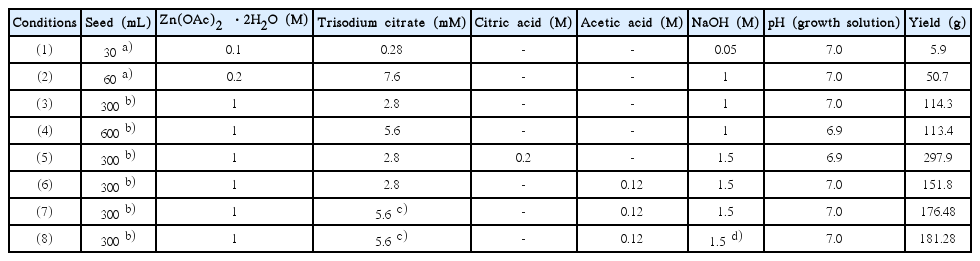
Changes in Seed and Growth Solution Properties for Large-Scale (3 L) Synthesis of Plate-Like ZnO. a),b)ZnO Seeds Were Synthesized Using Sphanhel and Hall Methods; c)Sodium Citrate was Dissolved in Seed Solution, which was then Added to Growth Solution; d)NaOH Solution was Added Slowly to Growth Solution Over 30 min67)
In the case of condition (2), the amount of NaOH was increased by a factor of 20 in order to increase the yield, while the pH of the growth solution was adjusted to 7.0 by increasing the amount of trisodium citrate added, in order to the prevent the formation of rod-like ZnO at higher pH values. Moreover, the seed solution was added after preparing the growth solution under neutral conditions to inhibit crystal growth and prevent the dissolution of the seed crystals under acidic and basic conditions. An SEM image (Fig. 23(b)) of the obtained product shows that the size of the plate-like ZnO crystals was not uniform, with many rod-like crystals also being formed. Nevertheless, the yield was 10 times higher, owing to the addition of a greater amount of NaOH to the growth solution. For conditions (3) – (8), ZnO seeds prepared by the Hale method were used. For conditions (3) and (4), the amount of NaOH used corresponded to a concentration of 1 M, while the amounts of zinc acetate dihydrate (Zn(OAc)2·2H2O) and trisodium citrate were adjusted to keep the pH of the growth solution neutral, as in condition (2). As a result, almost no rod-like ZnO particles were formed. However, the size of the plate-type ZnO crystals was still not uniform (Fig. 23(c) and (d)). Meanwhile, the yield increased significantly to approximately 110 g. For condition (5), the amount of NaOH added was increased to correspond to a concentration of 1.5 M, and citric acid was added to the growth solution to neutralize it. The yield, which was approximately 300 g, was the highest; however, large amounts of amorphous crystal impurities were observed (Fig. 23(e)). This confirmed that Zn-HDS is formed during the dissolution of the ZnO generated from citric acid.34) For condition (6), acetic acid was added to adjust the pH of the growth solution. As shown in Fig. 23(f), the plate-like ZnO crystals formed were non-uniform in size, and the yield was slightly lower at 152 g. However, no Zn-HDS formed due to the addition of citric acid. Similar to the case for condition (6), acetic acid was used to adjust the pH under condition (7). To effectively protect the (0001) plane of the seeds from the citrate molecules, trisodium citrate was added to the seed solution before the solution was added to the growth solution. The size of the obtained plate-like ZnO crystals was uniform (Fig. 23(g)). Further, the yield was approximately 177 g, which is 30 times higher compared to that for condition (1). The reaction conditions for condition (8) were the same as those for condition (7); however, the growth solution was prepared by adding the NaOH solution gradually over a period of approximately 30 min. As a result, uniform plate-like ZnO crystals were obtained, and the particle size was twice as large (see Fig. 23(h)). This suggests that the OH− ions reacted completely with Zn(OAc)2·2H2O owing to the gradual addition of NaOH, because of which the ZnO precursor, namely, Zn(OH)42− ions, formed with ease. Thus, condition (7) can be considered the most suitable one for preparing uniform plate-like ZnO crystals in a high yield. In this study, using this condition, uniform plate-like ZnO crystals could be formed in a yield of approximately 6.7 kg when the hydrothermal reaction was performed at a volume of 100 L in a 500 L reactor, as shown in Fig. 24. However, the yield should be increased further. In addition, the problem related to the increase in the particle size during pilot-scale synthesis should be investigated, and a synthesis method that does not require seeds should be developed, in order to further the industrial applicability of plate-like ZnO.
Pilot-scale (100 L) synthesis of plate-like ZnO crystals using high-capacity reactor (Easthill Inc.) and SEM images of resulting products.
7. Conclusions
Plate-like ZnO crystals prepared via controlled seed-based crystal growth exhibit better UV-lasing properties as compared to rod-like ZnO crystals, owing to the wide (0001) plane of the former. The excellent photocatalytic properties of plate-like ZnO are attributable to the numerous atomic defect sites present on the (0001) plane. In addition, the antibacterial mechanism of ZnO nanoparticles under dark conditions, which had remained unclear till now, was elucidated based on the crystallographic characteristics of plate-like ZnO. Pilot-scale synthesis of plate-like ZnO was achieved by the changing properties of the crystal growth solution and the seed synthesis method. However, the yield needs to be improved further, in order to increase the industrial applicability of plate-like ZnO. Further, while plate-like ZnO can be used in several industrial fields, including in photoelectronic devices, solar cells, photocatalysts, sunscreen lotions, and antibacterial agents, it is essential to explore its characteristics and applicability further.
Acknowledgments
This study was supported by a 2014 Research Grant (Project No. 2014-104-132) from the Kumoh National Institute of Technology.