Synthesis of ZrO2 Nanorods and Their Application as Membrane Materials
Article information

Abstract
Zirconia (ZrO2) materials are widely used in a variety of energy systems and devices. When nanorod-shaped ZrO2 is used as energy materials, ionic conductivity and mechanical strength can be improved compared to the characteristics of conventional spherical-shaped nanomaterials. In this study, we synthesized ZrO2 nanorods and investigated the shape change of them depending on various synthesis conditions such as precursor concentration, synthesis temperature, synthesis period, and aging period. The obtained nanorods were casted into a membrane for alkaline water electrolysis system and subjected to basic performance evaluation for use as a separator. The structure and the shape of the nanorods were characterized by X-ray diffraction (XRD), scanning electron microscopy (SEM), and the like.
1. Introduction
ZrO2 material is widely used in superplastic structural ceramics, transformation toughening, electrochemical devices, catalysis, and sensors due to its perfect crystallinity, large specific surface area, and small dimension.1–6) The moisture sensitivity is significantly increased when the material is synthesized into nanorods up to 8 nm in diameter and 22 nm in length. Among the literatures on the synthesis and applications of ZrO2 materials, few studies have examined nanorod-shaped ZrO2. In particular, the use of ZrO2 nanorods in electrodes and membranes can improve the ionic conductivity and the mechanical strength.7,8) To date, ZrO2 nanorods have been synthesized by annealing of a Zr precursor powder,9) concentration-dependent solution deposition,10) or chemical vapor deposition.11) These methods of synthesizing ZrO2 nanowires involve multi-step processes, most of which require high energy. This study employed hydrothermal synthesis to fabricate ZrO2 nanorods at low temperature levels. This method is more convenient and useful for mass production since the nanorods can be synthesized simply by optimizing conditions such as precursor concentration, synthesis temperature, and synthesis time.12,13) The synthesized nanorods were used as a material for the membrane of an alkaline water electrolysis system, and basic performances were tested. Alkaline water electrolysis technology is classified as a low-temperature technique, which uses electricity to split water molecules into hydrogen and oxygen,14–16) and has been developed to the level of commercialization.
Since membranes for alkaline water electrolysis are used in a strongly basic electrolyte (30% KOH), it is important to secure the chemical and mechanical stability of a membrane. Asbestos is a conventional and commercialized membrane material with a reasonable price and a porous structure. However, it shows poor durability in long-term reactions. For instance, they may experience a collapse in structure at higher temperatures than 100°C and in KOH concentration higher than 30%.5,7,17) Alternative materials to asbestos that have been proposed are porous ceramics such as potassium titanate, ZrO2, MgO, and TiO2,2) which are easily soaked in an electrolyte due to their hydrophilic nature and do not easily collapse due to their outstanding mechanical strength. However, they have the disadvantage of being less flexible against high mechanical strength. Another alternative material is the polymer membrane, which is flexible and has the advantage of being produced with thin thickness. Such membranes, however, are less durable at high temperatures or under strong alkaline conditions due to their weak mechanical strength.18) As such, researchers are focusing on developing composite materials that combine only the advantages of porous ceramics and polymer materials. To date, the most well-known membrane is Zirfon® manufactured by Agfa corporation. Zirfon® is a reinforced composite membrane that casts slurry mixed evenly with polysulfone (PS) polymer on top of polyphenylene sulfate (PPS) support. It remains durable under strong alkaline conditions, and hardly experiences any collapse in structure.19–21)
The purpose of this study is to replace the spherical nanoparticles used in the present Zirfon® membranes into the nanorodes, increasing the mechanical strength, flexibility, and reducing ion resistance.7,8,10,11) This study is meaningful to develop our own technology for manufacturing membranes for alkaline water electrolysis system. The structure and properties of ZrO2 nanorods were analyzed using scanning electron microscopy (SEM) and X-ray diffraction (XRD), and the performance of the membrane was evaluated in an alkaline water electrolysis system.
2. Experimental Procedure
2.1. Material
For the synthesis of ZrO2 nano rods, zirconium(IV) oxynitrate hydrate (Sigma Aldrich, 99%) was dissolved in distilled water at a concentration of 0.05 ~ 0.5 mol, and mixed with sodium hydroxide (NaOH, Samchun chemical 98%). For the fabrication of the membrane, ZrO2 nanorods obtained from hydrothermal synthesis were mixed with ZrO2 nanoparticles (−40 nm, US Research Nanomaterials, Inc.) in different proportions, and supported on a polyphenylene sulfide mesh (PPS, thickness of 203 μm, PVF mesh & screen technology). Polysuflone (PSU) (molecular weight of 35,000, Sigma-Aldrich, 99%) was dissolved in n-methy-2-pyrrolidon (NMP, Sigma Aldrich ≥ 99%) for the binding of the nanoparticles.
2.2. Synthesis of Zirconia Nanorods
The concentration of zirconium precursor (Zirconium oxyhydrate nitrate) aqueous solution was varied in the range of 0.01–0.05 mol, and that of the NaOH aqueous solution in the range of 10–20 mol. The zirconium oxyhydrate nitrate solution was mixed with the NaOH solution in a beaker, and ethanol was added to facilitate mixing of the solutions. The reactions proceeded for 8 to 72 h using sol-gel method. The mixing ratio was 30 ml of zirconium solution, 3 ml of NaOH solution, and 10 ml of ethanol. The precipitants obtained by hydrothermal synthesis were dispersed through ultrasonic treatment at room temperature for 30 min, and the solution was synthesized in an enclosed SUS reactor at 200–250°C for 24 h. After cooling down the heated reactants to room temperature, the solid sediments were collected. In order to clean the remaining precursors of the solids obtained, repeat the process of separating water from solid elements by centrifuging the specimens after filling them with water. Finally, the ZrO2 nanorods were obtained by drying the solids at 80°C for 12 h.
2.3. Membrane Fabrication
A ZrO2/polysulfone composite porous membrane was fabricated using the film-casting technique. After dissolving polysuflone in NMP at 50°C (PSU:NMP=82:18), ZrO2 nanoparticles were added to the solution to be about 80 wt.%. The ZrO2 used for fabrication were prepared by mixing nanorods, obtained from hydrothermal synthesis, with the commercial spherical powder at various proportions (spherical powder:nanorod=90:10, 95:5). The mixture was continuously agitated at a speed of 2,000 rpm at 50°C for 3 h until uniform viscosity was obtained. The suspension was cast into the form of membrane on a glass plate using a doctor blade having a gap size of 300°C. Using a polyphenylene sulfide mesh (PPS80PW, PVF) as a support layer with the suspension, the second cast was performed at a thickness of 600°C. The membrane was retrieved by dipping the casted glass sheet in deionized water at room temperature, and rinsed 2 ~ 3 times in deionized water before being used in the experiment.
2.4. Surface Characterization and Performance Evaluation
ZrO2 nanorods obtained from hydrothermal synthesis were analyzed using X-ray diffraction (XRD) (CuKα, Rigaku Model D/MAX 2500) and a scanning electron microscope (SEM, HITACHI S-4700, acceleration voltage of 20 kV). Bubble point pressure was measured to assess the durability when the membrane was subjected to pressure during the operation of water electrolysis system. For this purpose, a specially fabricated device was fixed onto the membrane to measure the pressure when the first bubble was formed by increasing the gas pressure at the bottom and filling the upper part with solvent such as water or alcohol. The ionic resistance per unit area of the membrane was measured by subtracting the cell resistance in the absence of a membrane from the cell resistance with the membrane in 30% KOH at 30°C and then multiplying by the area.
3. Results and Discussion
3.1. The Shape of Zirconia Nanorod Depending on the Synthesis Conditions
3.1.1. Effect of Precursor Concentration
ZrO2 nanorods were synthesized while varying the concentration of zirconium precursor and NaOH.
Figure 1 shows the XRD patterns of commercial ZrO2 nanoparticles (Fig. 1(a)) and ZrO2 nanorods obtained by hydrothermal synthesis at 200°C for 24 h (Fig. 1(b)).22) Based on JCPDS-65-1022 (pure ZrO2), JCPDS-80-0965, JCPDS-42-1164 (tetrahedral ZrO2), and JCPDS-37-1484 (monoclinic ZrO2), commercial ZrO2 nanoparticles (Fig. 1(a)) exist in pure monoclinic ZrO2 phase and partially in tetragonal ZrO2 phase. In the result of ZrO2 nanorods shown in Fig. 1(b), only pure monoclinic ZrO2 phase is observed, which is different from the commercial ZrO2 nanoparticles. The XRD analysis indicates that the commercial nanoparticles synthesized at higher temperatures contain both m-ZrO2 and t-ZrO2, while the lab-made nanorods consist of pure m-ZrO2.

XRD patterns of zirconium oxide nanoparticles and nanorods.
Synthesis conditions such as concentration of the precursor solution, synthesis temperature, synthesis time, and aging time were varied, and their effects on the shape of nanorods were examined. Fig. 2 shows SEM images of the nanorods under different concentrations of Zr precursor solutions while keeping the concentration of NaOH solution at 10 mol. As can be seen from the images, the powder is rod-shaped instead of spherical when the concentration of Zr precursor solution is in the range of 0.03 mol–0.5 mol. To enhance the understanding of the relationship between the concentration of the Zr precursor solution and the nanorod shape, the average aspect ratio of Zr nanorods was measured under different conditions and presented as a function of Zr concentration (Fig. 3). The synthesized ZrO2 nanorods had larger aspect ratios for less concentrated Zr solutions, and showed the greatest aspect ratio at a concentration of 0.1 mol. This can be traced to the hydrolysis rate of zirconium cations and the structure directing role of NaOH, which serves as a capping agent, in the synthesis of ZrO2 nanorods. That is, the hydrolysis rate of zirconium cations accelerates with increasing concentration of the Zr precursor, leading to the synthesis of rods with smaller aspect ratios as presented in Fig. 3. On the other hand, if Zr solution is less concentrated, the hydrolysis rate of zirconium cations slows down, and the resulting rods tend to have larger aspect ratios. Meanwhile, the aspect ratio decreases when the concentration of the Zr precursor solution falls below 0.1 mol, which is considered to be due to insufficient concentration of Zr precursor for nanorod synthesis. Regardless, the nanorods produced under this condition had relatively high aspect ratios in the range of 7–9.
SEM images of ZrO2 nanorods depending on the concentration of Zr(NO3)2 precursor solution (a) 0.01 mol, (b) 0.03 mol, (c) 0.05 mol, (d) 0.07 mol, (e) 0.1 mol, (f) 0.2 mol, (g) 0.3 mol, (h) 0.5 mol, (i) 1.0 mol (NaOH solution concentration: 10 mol, temperature: 200°C, synthesis time: 24 h).
Aspect ratio of ZrO2 nanorod depending on Zr(NO3)2 solution concentration (NaOH solution concentration: 10 mol, temperature: 200°C, synthesis time: 24 h).
While maintaining the concentration of the zirconium precursor solution at 0.5 mol, the shapes of ZrO2 nanorods depending on the NaOH concentration were observed by SEM (Fig. 4), and the aspect ratio of the Zr nanorods was measured for each case (Fig. 5). The aspect ratio is 2.1 at an NaOH solution concentration of 7 mol, 5.56 at a concentration of 10 mol, and 6.8 at a concentration of 12 mol, and peaked at a concentration of 10–12 mol. During hydrothermal synthesis, Zr precursors existing as Zr-NO3-Zr experienced hydrolysis in the presence of NaOH, resulting in Zr-NO3-Na and Zr-OH bonds. At this point, increasing the NaOH concentration raises the pH of the solution and promotes hydrolysis. Surface energy is lowered with strong adsorption of these bonds on the m-ZrO2 surface, and ZrO2 crystals grow in the lengthwise direction. That is, the higher the concentration of NaOH is, the greater the aspect ratio of the nanorods will be.23) However, if the concentration of NaOH exceeds a certain level, NaOH acts as a capping agent in the mixture, thus causing a decrease in the aspect ratio.
SEM images of ZrO2 nanorods depending on the concentration of NaOH solution (a) 5 mol, (b) 7 mol, (c) 10 mol, (d) 12 mol, (e) 15 mol and (d) 20 mol (ZrO2 solution concentration: 0.5 mol, temperature: 200°C, synthesis time: 24 h).

Aspect ratio of ZrO2 nanorods depending on NaOH solution concentration (ZrO2 solution concentration: 0.5 mol, temperature: 200°C, synthesis time: 24 h).
To obtain ZrO2 nanorods with optimal shapes, it is important to optimize not only the production rate of Zr cations and the hydrolysis rate due to NaOH addition, but also the aspect ratio of the resulting nanorods. In this study, the optimal synthesis conditions that maximized the aspect ratio were a Zr precursor concentration of 0.2–0.5 mol and a NaOH solution concentration of 10–12 mol. Under these conditions, the BET surface area of the obtained nanorod powder was 17.8 m2/g.
3.1.2. Effects of Reaction Time, Aging Time, and Reaction Temperature
To optimize the shape of the Zr nanorods, the aspect ratio of the nanorods was measured after varying conditions such as hydrothermal synthesis time, subsequent aging time at room temperature, and reaction temperature. In this case, the concentration of the Zr precursor solution was kept at 0.5 mol, and that of the NaOH solution at 10 mol. Fig. 6(a) gives the aspect ratio of ZrO2 nanorods obtained from varying the synthesis temperature in the range of 150–250°C. The aspect ratio increases with synthesis temperature, and remains similar after 200°C. That is, the aspect ratio of the nanorods was 3.2 when they are synthesized at 150°C, 5.5 when synthesized at 200°C, and increased up to 6.0 when synthesized at 250°C. Fig. 6(b) shows the aspect ratio in relation to synthesis time, varied from 8 to 72 h. The aspect ratio was about 6 regardless of the synthesis time, indicating that the shape of the nanorods is unaffected by synthesis time, but more directly influenced by other factors such as synthesis temperature and precursor concentration. Fig. 6(c) shows the lengthwise growth of nanorods with additional aging treatment, and aging time was found to have little influence on the growth of the rods. Consequently, aging time and reaction time did not affect the shape of the nanorods, and synthesis temperature was insignificant in the range of 200–250°C. Based on these results, subsequent synthesis processes were carried out at a reaction temperature of 200°C for 24 h with no aging treatment. The nanorods used for the membrane casting in this study had an aspect ratio of approximately 5.5. Membrane performance may be improved to further extent by replacing nanorods with those having a larger aspect ratio. The nanorods in this study had an average width of 45 nm, length of 257 nm, and aspect ratio of 5.5.
Effect of (a) synthesis temperature, (b) synthesis time and (c)aging time on the aspect ratio of ZrO2 nanorods (concentration of Zr(NO3)2 solution 0.5 mol, NaOH concentration 10 mol).
3.2. Evaluation of Membrane Performance in Zirconia Nanorods
Membranes were made by mixing ZrO2 nanorods with ZrO2 spheres at fixed proportions, and basic performances were evaluated for application in an alkaline water electrolysis system. Commercial ZrO2 spheres and ZrO2 nanorods were mixed in two different ratios: 90:10 and 95:5. Fig. 7 presents SEM images of (a) a commercial Zirfon membrane and (b) a lab-made membrane containing 10% nanorods. As shown in the SEM images, the particles in (b) are less uniformly coated and have more amount of empty spaces compared to the commercial Zirfon membrane. Such spaces may weaken the mechanical strength of the membrane and provide less control over gas permeation, and thus additional improvement of the manufacturing methods is considered necessary.

SEM images of ZrO2 membrane, (a) commercial Zirfon membrane (left) and (b) lab-made ZrO2 membrane (ZrO2 nanorod 10%+ZrO2 sphere) (right)
In order to evaluate the physical property of the membrane, bubble point and ionic resistance were measured, and the results were compared to those of a commercial Zirfon membrane. As shown in Table 1, commercial ZrO2 nanopowder and ZrO2 nanorods mixed in a ratio of 9:1 showed a bubble point of 0.3 bar, which was far lower than that of the Zirfon membrane (3 ± 1 bar). When ZrO2 nanorods were mixed at 5 wt.%, the bubble point increased to around 0.8 bar, which is improved compared to the value obtained by adding 10 wt.% nanorods. However, this value was still much lower than that of the existing membrane. The membrane produced with 10% nanorods had an ionic resistance of 0.086 Ω·cm2, while the membrane with 5% nanorods had a higher ionic resistance of 0.18 Ω·cm2. Both were higher than that of commercial Zirfon, which recorded a value smaller than 0.3 Ω·cm2. As can be deduced from the SEM images, membranes prepared by mixing nanorods have a less uniform surface and are more prone to cracks, which contribute to a lower bubble point. In follow-up studies, membrane performance can be improved by optimizing the mixing ratio and the shapes of nanorods (aspect ratio, length, thickness, etc.) according to the required membrane performance. Another approach to improve membrane performance is to increase the wettability of the nanorod surface. Meanwhile, the ionic resistance of the membrane significantly dropped due to the mixing of nanorods, because the nanorods have higher ionic conductivity than spherical powder. In conclusion, by applying the ZrO2 nanorod material to the alkaline water electrolytic separator, it is possible to produce a membrane having excellent mechanical strength and excellent ion conductivity.
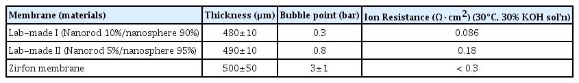
Basic Characteristics of ZrO2-Nanorod Membrane
4. Conclusions
Based on the ZrO2 materials widely used in various energy materials and devices, the ZrO2 nanorods were synthesized in a simple process at low temperature. The applicability of these nanorods as a membrane material of the alkaline water electrolysis system was evaluated. The shape and the aspect ratio of the ZrO2 nanorods were affected by the composition and the concentration of the precursors and the synthesis temperature. The synthesis conditions that allowed the formation of nanorods with a maximum aspect ratio were a Zr precursor solution concentration of 0.2–0.5 mol and a NaOH aqueous solution concentration of 10–12 mol.
The synthesized nanorods were mixed with a commercial spherical nanopowder at fixed proportions to fabricate the membrane for an alkaline water electrolysis system. Basic properties such as bubble point and ionic resistance were measured. The bubble point tends to decrease when ZrO2 nanorods are mixed with the commercial nanoparticles, and this is presumed to be due to the structural non-uniformity of the lab-made membrane. The desired bubble point may be attained by optimizing the surface wettability of nanorods, aspect ratio, length, and thickness in our subsequent research. The ionic resistance of the membrane dropped due to the mixing of nanorods because which have higher ionic conductivity than conventional spherical ZrO2. Based on these results, the performance of membrane for alkaline water electrolysis system may be further improved through surface modification and shape optimization of the ZrO2 nanorods.
Acknowledgments
This work was supported by Technology Development Program to Solve Climate Changes through the National Research Foundation of Korea (NRF) funded by the Ministry of Science, ICT (NRF-2016M1A2A2940138 and NRF-2015M1A2A2074657).