Recent Progress in Flexible Perovskite Solar Cell Development
Article information
Abstract
Perovskite solar cells (PSCs) are a new class of photovoltaic devices, which have attracted significant attention due to their remarkable optoelectrical properties, including high absorption coefficients, high carrier mobilities, long carrier diffusion lengths, tunable bandgaps, low cost, and facile fabrication. PSCs have reached efficiencies of 22.70% and 18.36% on rigid fluorine-doped tin oxide and poly(ethylene terephthalate) substrates, respectively; these are comparable to those of single-crystal silicon and copper-indium-gallium-selenium solar cells. Over the past eight years, the photo conversion efficiency of PSCs has been significantly improved by device-architecture adjustments, and absorber and electron/hole transport layer optimization. Each layer is important for the performance of PSCs; hence, we discuss achievements in flexible perovskite solar cells (FPSCs), covering electron/hole-transport materials, electrode materials. We give a comprehensive overview of FPSCs and put forward suggestions for their further development.
1. Introduction
Due to their excellent optoelectrical properties, such as long diffusion lengths, strong absorptivity, high carrier mobilities, low defect densities, and tunable bandgaps, perovskites have drawn significant attention as promising alternative absorber materials for optoelectronic devices–especially for use in perovskite solar cells (PSCs), where the efficiency has risen to 22.70%1) (certified) and 18.36%2) on rigid-glass and flexible-polymer substrates, respectively. This is comparable to the efficiencies of single-crystal silicon and copper-indium-gallium-selenium (CIGS) solar cells. Recently, numerous studies of these materials have been published. The typical structure of a PSC is a transparent conducting oxide (TCO) substrate followed by an electron-transport layer (ETL), the perovskite, a hole-transport layer (HTL), and a metal electrode. The recent increase in efficiency is ascribed to modifications to the device structure and optimization of the material compositions.
Perovskite materials were originally used as a sensitizer in dye-sensitized solar cells. Miyasaka’s group employed a CH3NH3PbBr3 sensitizer and obtained an efficiency of 3.8%.3) However, CH3NH3PbBr3 was very unstable in iodide-containing liquid electrolytes, which causes the device to degrade rapidly. In 2011, Park’s group fabricated quantum-dot-sensitized solar cells using pre-synthesized perovskite materials of 2 – 3 nm in diameter. A photoconversion efficiency (PCE) of 6.54%, attributed to the high absorptivity of the CH3NH3PbI3 quantum dots and the low current loss of the thin TiO2 film, was achieved.4) In 2012, Park et al. fabricated solid-state, sensitized, heterojunction perovskite solar cells for the first time (device structure: fluorine-doped tin oxide (FTO), TiO2 blocking layer, mesoporous TiO2 perovskite, 2,2′,7,7′-tetrakis (N,N-di-pmethoxyphenylamine)-9,9′-spirobifluoren (spiro-OMeTAD), Au); the highest efficiency, 9.7%, was obtained by optimizing the layer thicknesses. The most important development was a remarkable improvement in device stability: it was air stable for over 500 h without encapsulation.5) This is a milestone for PSC development, enabling further performance improvements. As it achieves a high PCE, this structure has been widely adopted by other researchers.
Another breakthrough, achieved by Snaith’s group, was the development of low-cost, solution-processable PSCs with a PCE of 10.9%; this was the highest PSC PCE then measured. In their study, TiO2 was replaced with insulating mesoporous Al2O3.6) They also revised understanding of PSC device structures by proposing a new PSC structure, known as the planar structure. Their results showed that nano-structuring is not required to achieve high PSC efficiencies. They prepared a CH3NH3PbI3-xClx perovskite film by dual-source evaporation and sandwiched this between a planar ETL and a planar HTL; the PCE of this system reached 15.4%, with a Voc of 1.07 V, a Jsc of 21.5 mA cm−2, and an FF of 0.67.7) Now, PSC structures are divided into two categories: mesoporous and planar.
Many strategies for PSC fabrication have been introduced, with the aim of improving PSC performance–these include solvent engineering,8,9) employment and doping of new transport materials,10–13) addition of additives in the perovskite film,14) interface engineering,15) tuning the perovskite film composition,16) and various different preparation techniques.17,18) Current state-of-the-art PSC efficiencies are 22.70% and 19.70% with active areas of 0.095 cm2 and 1.0 cm2, respectively; these are obtained using (FAPbI3)1-x (MAPbBr3)x mixed perovskite films as absorbing layers.19) However, most high-efficiency PSCs utilize rigid substrates, which are heavy, inflexible, and fragile. Flexible PSCs for large-area, modular devices can be easily fabricated using the roll-to-roll technique and easily match the shapes of portable electronic products.20) Due to these benefits, flexible PSCs are an active area of research. Several types of flexible solar cells have been reported, including: silicon-based flexible solar cells, for example silicon-based thin-film solar cells;21–24) compound flexible solar cells, such as CIGS,25,26) and CdTe;27,28) organic solar cells;29–31) dye-sensitized solar cells;32,33) and organic-inorganic hybrid solar cells, for example perovskite solar cells.13,34) In this review, we will cover recent progress in the field of flexible perovskite solar cells. A typical PSC device consists of five key components: the TCO substrate, ETL, active perovskite layer, HTL, and rear electrode. PSC device structures are classified into regular and inverted planar structures, based on their stacking sequence. In this review, we will cover the state-of-the-art in flexible PSCs (FPSCs) from the viewpoint of the aforementioned cell structures and components.
2. Flexible Perovskite Solar Cells
The exhilarating results have been achieved for most of the popular solar cells based on the rigid substrates. However, rigid substrates have numerous drawbacks, such as their weight, frangibility, and rigidity, which prevent them from satisfying the demands of modern flexible electronic devices; as flexible solar cells do not possess these drawbacks, they have attracted significant attention.
As they are solution processable and have low fabrication temperatures (< 150°C), simple structures, and high efficiencies, FPSCs have a promising future. In recent years, there has been significant progress in FPSC technology, with PCEs of up to 18.40% achieved,35) hugely exceeding the PCEs of other flexible solar cells. FPSC devices have the same structure as rigid devices, and can also be divided into planar and mesoporous architectures. In the following sections, recent advances in FPSC ETLs, HTLs, and electrodes will be discussed.
2.1. FPSCs based on planar architectures
Transparent polyethylene terephthalate (PET) and polyethylene naphthalate (PEN) polymers coated with indium tin oxide (ITO) are widely used flexible substrates. The main drawback of this type of flexible, conductive substrate is that they cannot withstand high-temperature annealing (> 150°C). However, most high-PCE PSC devices are based on TiO2 ETLs, particularly mesoporous structures; in this case, a high temperature (> 450°C) annealing process is still required to obtain high quality TiO2 for electron transport. This high-temperature process is incompatible with the low thermal stability of the flexible substrate. To overcome this, numerous strategies have been exploited for the preparation of TiO2 ETLs on ITO-PEN/PET substrates, including chemical sintering,36) plasma-enhanced atomic layer deposition (PEALD),37,38) chemical vapor deposition,39) radio frequency magnetron sputtering deposition (RFMSD),40,41) and electrophoretic deposition.42) Atomic layer deposition is often used to deposit high-quality, stoichiometric, dense, pinhole-free thin films.
In 2014, Jung and co-workers used low-temperature PEALD of a titanium(IV) isopropoxide precursor to deposit a 20 nm thick, amorphous, cp-TiOx layer on a PEN/ITO substrate; the film was then annealed at 80°C for 15 min, achieving a PCE of 12.2%, a high efficiency for the planar configuration (Fig. 1).38) In 2015, Brown and co-workers reported low-temperature, flexible PSCs with a mesoporous architecture; they used cyclopentadienyl alkylamido titanium, Ti(CpMe)(NMe2)3, as the precursor to deposit cp-TiO2 on PET/ITO substrates via PEALD; following this, spin coating was used to prepare mesoporous TiO2 scaffolds and the high-temperature annealing replaced by UV irradiation to remove the organic binders. These PSCs exhibited a PCE of 8.4%.43) Liu’s group used room-temperature RFMSD to deposit a dense, amorphous TiO2 (am-TiO2) film to serve as an ETL in planar, flexible PSCs with efficiencies up to 15.07%.40) The good performance of the ETL-based PSCs is attributed to improved electron extraction and reduced transfer resistance (Fig. 2).

(a) Cross-sectional SEM image and structure of the FPSCs. Scale bar: 200 nm. (b) Normalized PCE measured after bending the substrate from a radius of 1 mm to a radius of 400 mm. Inset: photographs of the FPSCs attached to a human neck, wrist, and finger, corresponding to 400 mm, 10 mm and 4 mm bending radii, respectively. (c) Normalized PCE of FPSCs as a function of number of bending cycles with radii of 400 mm, 10 mm, and 4 mm. The error bars represent the standard deviation of 4 tests. Inset: photographs of the bending tests. Reprinted with permission from ref. 40. Copyright 2015 Royal Society of Chemistry.

(a) Structure of the planar PSCs. (b) HRTEM image and electron diffraction pattern (inset) of the as-deposited TiO2 film. (c) Energy-level diagram of the components of the PSCs with anatase TiO2 and am-TiO2 ETLs. (d) Photograph of an FPSCs. (e) J-V curves of the rigid and flexible devices with an-TiO2 am-TiO2 ETL and the flexible device before and after 100 bending cycles. (f) IPCE curves of the rigid and flexible PSCs. (g) PCE distribution histogram for the FPSCs. Reprinted with permission from ref. 36. Copyright 2015 Royal Society of Chemistry.
Other inorganic and organic compounds used as ETLs in normally structured PSCs include ZnO,10,44,45) WO3,46) In2O3,47) CuInS2,47) SnO2,48) CdSe,49) Zn2SnO4,50,51) Nb2O5,34) and C60,49) which are synthesized at low temperatures. For instance, Liu’s group used low-temperature electron-beam thermal evaporation to deposit a Nb2O5 thin film on a PET/ITO substrate, and, thus, obtained PCEs of up to 14.6% for their planar, FPSCs (Fig. 3).34) Yang et al. introduced solid-state ionic liquids (ss-ILs) (1-benzyl-3-methylimidazolium chloride) into planar-structured, flexible PSCs as ETLs, resulting in the highest PCE of 16.09% in publication year.13) They attributed this excellent performance to the superior photoelectric properties, such as low reflectivity, high electron mobility, low trap density, and favorable work function, of the ss-IL ETL. The notorious hysteresis phenomenon is almost eliminated by these attributes, and the devices show mechanical robustness after 300 cycles of repeated bending over different diameters (Fig. 4).

(a) Cross-sectional view of a complete device based on ss-IL ETM. Inset: photograph of the FPSCs. (b) J-V curves and (c) IPCE plots of the FPSCs with and without the ss-IL ETM. (d) PCE distribution histogram of the FPSCs based on ss-IL ETM. (e) J-V curves of a device after bending at curvature radii of 12 mm, 7 mm, and 5 mm for 300 cycles. Reprinted with permission from ref. 13. Copyright 2016 John Wiley & Sons.
Owing to its wide band gap, high conductivity, facile solution processible, and thermal stability, ZnO has been extensively used in photovoltaic devices. For example, Kumar et al. reported a conversion efficiency of 2.62% for normal FPSCs comprised of PET/ITO/ZnO/ZnO-rod/MAPbI3/Spiro-OMeTAD/Au,44) and Liu et al. reported a conversion efficiency of 10.2% for PET/ITO/ZnO/MAPbI3/spiro-OMeTAD/Ag FPSCs.10) Yang’s group developed a low-temperature (150°C) spin-coating process to prepare highly transparent, uniform ZnO ETLs for FPSCs; after modification with urea, the perovskite film quality improved significantly, resulting in PCEs of up to 11.9%.52) By spin-coating a ZnO nano-sol solution, Im’s group prepared high quality ZnO thin films as an effective ETL for FPSCs; ZnO-based flexible devices fabricated on a PEN/ITO substrate achieved an average PCE of 15.5% and exhibited considerable mechanical stability (Fig. 5).45)
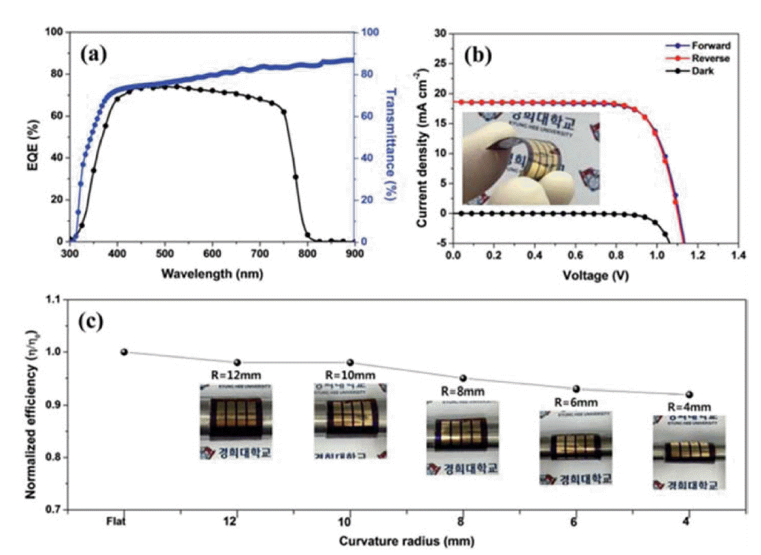
(a) External quantum efficiency spectrum of the PEN/ITO/ZnO/MAPbI3/PTAA/Au FPSCs and transmission spectrum of the PEN/ITO substrate. (b) J-V curves of FPSCs under illumination of 1 Sun. Inset: photograph of the FPSCs. (c) Normalized PCE of FPSCs at bending radius R. Reprinted with permission from ref. 45. Copyright 2016 Royal Society of Chemistry.
Other inorganic compounds can also be exploited in PSCs. Shin et al. reported conversion efficiencies of up to 15.3% for PEN/ITO/Zn2SnO4/MAPbI3/PTAA/Au FPSCs.50) They also reported that tailoring of the energy levels, by adjusting the Zn2SnO4 NPs grain size, increased the efficiency to 16% under AM 1.5G illumination with an intensity of 100 mW cm−2 (Fig. 6).53)
Due to its large band gap, high transparency, and high carrier mobility, SnO2 has attracted significant attention as a potential replacement for cp-TiO2 in PSCs. Miyasaka’s group used a mesoporous-brookite TiO2 layer, with amorphous SnOx as an ETL, deposited on an ITO/PEN substrate below 150°C to achieve PCEs of up to 13.4% and hysteresis-free J-V curves.54) Yan’s group reported the use of PEALD to prepare SnO2 thin films at 100°C on a PET/ITO flexible substrate; the efficiency up to 16.8% was obtained using C60 self-assembled-monolayer passivation of the SnO2 surface.48) Despite the high efficiency, the as-deposited SnO2 film was not completely transformed, and organic residues were present. Thus, water vapor was introduced during the annealing process to facilitate completion of the reaction. With the water-vapor treatment, the electrical conductivity of the SnO2 film improved, and the resulting FPSCs exhibited dramatic improvements in Voc and FF, no J-V hysteresis, and an increase in the PCE to 18.36%; the highest reported efficiency for FPSCs with a regular architecture. They also exhibited mechanical robustness during 1000 cycles of repeated bending (Fig. 7).2)
2.1.1. FPSCs based on the inverted architecture
The need to withstand high temperatures, impedes the utilization of cp-TiO2 in FPSCs devices which prepared by conventional approaches; thus, most FPSCs based on ITO/PET and PEN substrates are fabricated in the inverted planar architecture. In this configuration, poly(3,4-ethylenedioxythiophene) polystyrene sulfonate (PEDOT:PSS) is the most frequently used HTL, [6,6]-phenyl-C61-butyric acid methyl ester (PCBM) is the most popular ETL, and the whole device can be fabricated at under 150°C. In 2013, Snaith’s group developed a device with a PET/ITO/PEDOT:PSS/MAPbI3-xClx/PCBM/TiOx/Al structure and obtained a high PCE of > 6%.55) In 2014, Lee’s group introduced the copolymer tetrafluoroethylene-perfluoro-3,6-dioxa-4-methyl-7-octene-sulfonic acid as an HTL for inverted FPSCs, resulting in PCEs as high as 8%.56) In the same year, Bolink’s group used Al-doped ZnO (AZO)/Ag/AZO coated PET as a flexible substrate, PEDOT:PSS and poly(4-butylphenyldiphenylamine) as the HTM, and PCBM as ETM, displayed PCEs up to 7% (Fig. 8(a)).57) The important thing is that the PCE declines by only 0.1% after 50 bending cycles. In 2015, Kelly’s group prepared high-conductivity, high-transmittance, high surface-coverage PEDOT on PET substrates to replace ITO, improving the mechanical properties of the FPSC device, and obtained a PCE over 7.6% and almost no hysteresis (Fig. 8(b)).58)

(a) Schematic of the FPSCs and chemical structure of the materials used as the electron and hole blocking layers. Reprinted with permission from ref. 57. Copyright 2014 Royal Society of Chemistry. (b) Structure of the FPSCs, bent at a radius of curvature, r. Reprinted with permission from ref. 58. Copyright 2015 Royal Society of Chemistry.
Although PEDOT:PSS is widely used as an HTM for inverted PSCs, its low conductivity hinders its development. Researchers have used surface modification and doping to improve its conductivity, and then increase FPSCs efficiency. Chen et al. prepared a self-assembled monolayer of 3-aminopropanoic acid on a PEDOT:PSS surface to modify the crystallinity and coverage of the perovskite film, resulting in an increase in PCE from 3.7% to 5.1%.59) Jang et al. introduced silver trifluoro-methanesulfonate (AgOTf) doped graphene oxide into PEDOT:PSS to improve the charge collection; FPSCs fabricated on a PET/ITO substrate showed a PCE of 9.67%.60) Bauer’s group introduced a thin layer of Cr2O3-Cr between the top metal electrode and the HTL, preventing diffusion of the metal and air into the perovskite film, which significantly increased device stability and achieved a high PCE of over 13% and a power-per-weight of 23 W g−1. They successfully used these ultra-lightweight perovskite solar cell devices to power a model aircraft (Fig. 9).61)
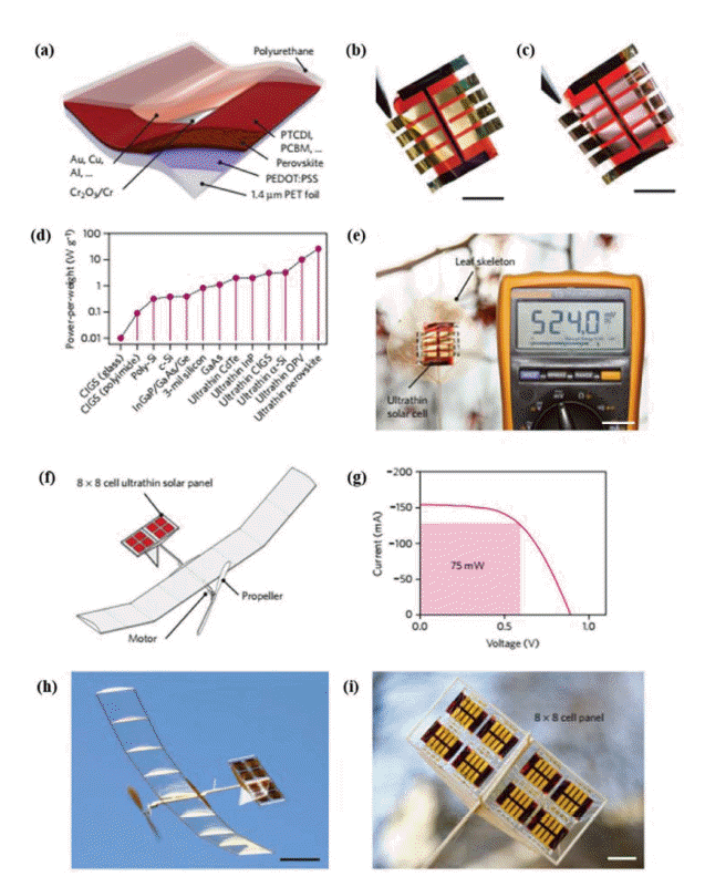
(a) Schematic diagram of FPSCs. (b) and (c) photograph of FPSCs with gold and copper as top and back electrodes, respectively. Scale bar: 1 cm. (d) The power-per-weight of different flexible solar cells. Ultrathin PSCs is more than double the nearest competing photovoltaic technology. (e) Dried leaf skeleton covered with a solar array of eight cells. The solar leaf (with a 100 Ω load) delivers ~ 2.75 mW under ~ 30 klx solar irradiance (Supplementary Movie 1). Scale bar: 2 cm. (f) Schematic drawing of the solar-powered model airplane. The ultralight solar panel (red rectangles) is integrated into the horizontal stabilizers and powers a direct current (DC) motor with a propeller. (g) Power output of the 64-cell solar panel. Under simulated AM 1.5 solar irradiance, the panel outputs 75 mW at max power point and powers the DC motor of the model aircraft effectively under ambient outdoor illumination (~ 40 klx). (h) Snapshot of the model plane during solar-powered outdoor flight (Supplementary Movie 3). Scale bar: 10 cm. (i) Close-up photograph of the horizontal stabilizer with integrated solar panels. Scale bar: 2 cm. Reprinted with permission from ref. 61. Copyright 2015 Nature Publication Group.
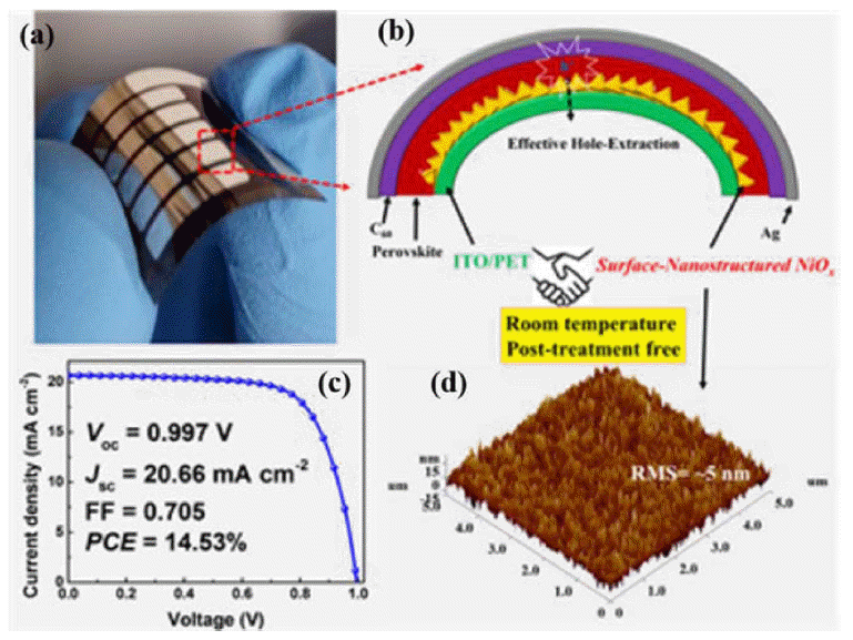
NiOx is another frequently used HTM. Choy’s group exploited spin-coating of an NiOx nanocrystal ink to develop a controllable route to surface-nanostructured NiOx for use as an HTM in FPSCs; the surface nanostructure provides a large interfacial area, effectively increasing hole extraction. Consequently, a remarkable efficiency of 14.53% was obtained (Fig. 10).62) Shao’s group developed a new technique to fabricate NiOx nanoparticles at 80°C; the NiOx film, prepared by spin coating pre-synthesized NiOx nanoparticles onto a PEN/ITO substrate and baking at 130°C, achieved a preliminary PCE of 13.43%.
Other HTMs have also been developed and used in inverted FPSCs, including CuyCrzO2,63) CoN,64) CuI,65) and other synthesized inorganic and organic compounds.
In 2017, Fang’s group used a CuyCrzO2 film as an HTM for flexible PSCs on a PET/ITO substrate prepared by the sol-gel method at temperatures as low as 140°C and achieved PCEs of up to 15.36% (Fig. 11).63)
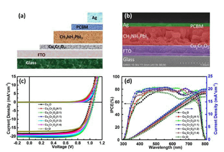
(a) Schematic and (b) cross-sectional SEM image of a PSC using a CuyCrzO2 film. (c) Illuminated J-V characteristics, and (d) IPCE spectra (black) and the calculated integrated photocurrent (blue) of devices based on the CuyCrzO2 HTL films with different volume ratios (y : z = 1 : 0, 4 : 1, 2 : 1, 1 : 1, 1 : 2, 1 : 4, and 0 : 1). Measurements were carried out under illumination of 1 sun (AM 1.5 G, 100 mW cm−2) with sweeping voltages in the scan-direction at a rate of 0.1 V s−1. The scans start and finish under forward bias, and have 2 s of stabilization time under illumination at forward bias prior to scanning. Reprinted with permission from ref 63. Copyright 2017 John Wiley & Sons.
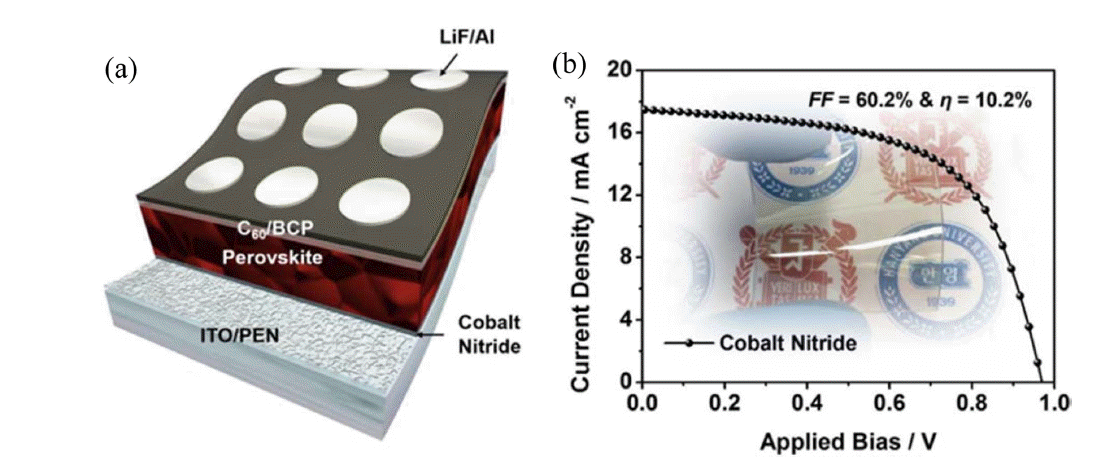
In 2016, Ko and Son’s group adopted 1,4-bis(4-sulfonatobutoxy) benzene and thiophene moieties (PhNa-1T) as an HTL for inverted FPSCs, with initial PCE of up to 14.7% it can effectively enhance device performance, such as morphology, charge extraction, and, especially, mechanical properties. The PhNa-1T-based FPSC PCEs remained at 60% of their initial values after 600 bending cycles (Fig. 12).66) In 2017, Kang et al. fabricated a CoN film on an ITO/PEN substrate, as an HTM for inverted PSCs, using room-temperature vapor deposition and obtained an initial PCE of 10.2% (Fig. 13).64)
2.1.2. Electrodes
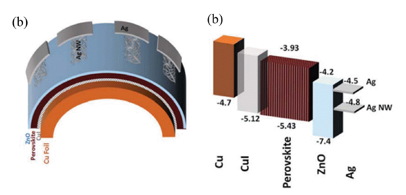
The electrode is an integral and essential component of a PSC, which includes top electrode and bottom electrodes. Noble metals, such as Au,13,34) Ag,67) and occasionally, Al68–70) are used for the top electrode. TCO, such as ITO, FTO, and AZO,71,72) are widely used as the bottom electrode. ITO is widely used as the bottom electrode in FPSCs deposited on PET and PEN polymer substrates. Although high efficiencies have obtained using PET and PEN/ITO bottom electrodes, the performance of the ITO films significantly decreases after repeated bending. Some studies have focused on overcoming this weakness by using metal foils to replace PET and PEN/ITO as the substrate and bottom electrode. In 2015, Jun’s group fabricated semi-transparent FPSCs on Ti foil, the device structure is Ti foil/cp-TiO2/mp-TiO2/perovskite/Spiro/ultra-thin silver, and they showed PCE of over 6%; the low efficiency was ascribed to the low transmittance of the Ag film (Fig. 14(a), (b)).73) Watson’s group overcame this issue using a PET/Ni-mesh top electrode tightly interwoven with PEDOT:PSS using a transparent conducting adhesive; both the transmittance and mechanical properties were improved, achieving a PCE of 10.8% (Fig. 14(c), (d)).74) Ahmadi’s group prepared FPSCs using copper foil both as the substrate and as the precursor for the CuI HTM; the device structure was Cu/CuI/perovskite/ZnO/Ag nanowires, resulting in PCEs of up to 12.8% (Fig. 15).65) Ag nanowires have also been used as a bottom electrode.67,75,76) For example, Choy’s group reported the use of a room-temperature, solution-processed nano-composite, composed of a silver nano-network and graphene oxide film, as the bottom electrode for PSCs. Graphene oxide films not only improve the electron-extraction efficiency, but can also protect the silver network from liquid and gaseous halides. A PCE of 7.92% was obtained.75)
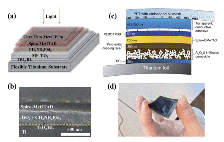
(a) Structure of perovskite solar cell using a titanium ultra-thin metal foil substrate. (b) Cross-sectional image of the complete cells. J. Mater. Chem. A, 2015, 3, 4129–4133. (c) Schematic representation of a metal-mounted perovskite solar cell and associated target-layer thicknesses. (d) Photograph of a flexible perovskite solar cell on titanium foil. (a–b) Reprinted with permission from ref 73. Copyright 2015 Royal Society of Chemistry. (c–d) Reprinted with permission from ref. 74. Copyright 2015 Royal Society of Chemistry.
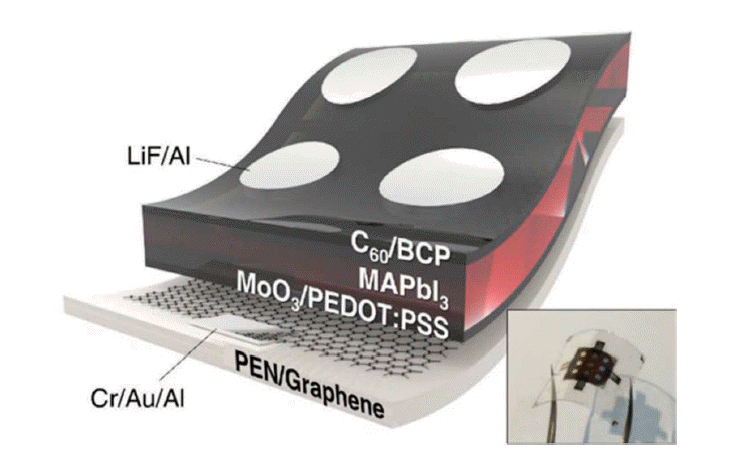
Carbon nanomaterials are also used as electrodes in flexible PSCs.69,77,78) In 2017, Jeon et al. used single-wall carbon nanotubes (SWNTs) as bottom electrodes for flexible PSCs. The device structure was PEN/SWNT/MoO3/PEDOT:PSS/perovskite/BCP-C60/LiF/Al; it exhibited high mechanical robustness and had a PCE of 11.0% (Fig. 16).77) Guo and colleagues employed an SnO2-coated carbon nanotube (SnO2@CSCNT) film as a top electrode for flexible PSCs. The device structure was PEN/ITO/NiO-perovskite/Al2O3-perovskite/SnO2@CSCNT-perovskite, and they exhibited a PCE of 10.5%; the device PCE remained at 91% of its original value after 550 h continuous illumination.78) Choi’s group used graphene as a bottom electrode for flexible PSCs. The device structure was PEN/Cr-Au-Al/graphene/MoO3/PEDOT:PSS/perovskite/C60/BCP/LiF/Al, and the complete devices showed superb stability against bending, maintaining > 90% of their initial efficiency after 1000 bending cycles and 85% after 5000 bending cycles (with a bending radius of 2 mm) (Fig. 17).69)
3. Conclusion and Outlook
We have briefly summarized state-of-the-art FPSC structures, transport materials, and electrodes. PSCs are promising alternatives to silicon-based solar cells due to their superior optoelectrical properties, low-cost, and high-efficiency. They are especially promising as flexible solar cells, which are promising power solutions for future portable devices. Substantial work has been done to improve FPSCs performance; for example, exploiting low-temperature fabrication routes for high-efficiency metal-oxide electron/hole transport materials (e.g., ZnO, SnO2, Nb2O5, and NiOx); improving the conductivity of PEDOT:PSS via modification; improving the mechanical properties of flexible substrates (e.g., Ag nanowires, AZO/Ag/AZO, and HC-PEDOT:PSS coated PET substrates). Currently, the highest FPSCs PCE is 18.36%, which was achieved with a PET/ITO substrate; however, the active area was only 0.08 cm2. In addition to the flexibility and efficiency, large scale and stability must also be considered. For large areas, methods including roll-to-roll printing, slot-die coating, sequential vacuum deposition, doctor blade printing, and spray coating have been exploited, and are promising routes for the preparation of large-scale FPSCs. Several strategies have been used to improve FPSC stability, including introduction of inorganic transport materials, passivation of internal and surface defects of the perovskite film, and use of stable electrode materials. Currently, no device can exhibit high efficiency, large surface area, and high stability, even at laboratory scales. Therefore, large-scale, high-efficiency and stability of FPSCs remain an important research target, and more in-depth research is necessary to achieve the aim of combing high efficiency, large surface area, and high stability into a single FPSCs.
Acknowledgments
This work was financially supported by the Global Frontier R&D Program of the Center for Multiscale Energy Systems (2012M3A6A7054855), the Basic Science Research Program of the National Research Foundation of Korea (NRF-2014R1A4A1008474), a National Research Foundation of Korea grant funded by the Korean government (MSIP) (No. 2017R1A2B3010927), and the Future Materials Discovery Program (NRF-2016M3D1A1027664).


