Fabrication of Mixed and Patterned Type of Remote Phosphors by Screen Printing Process and their Optical Properties
Article information
Abstract
Recently, white LEDs, especially, warm white LEDs have been intensively investigated due to outstanding optical properties, long term stability and low power consumption. In this study, mixed type and patterned type of remote phosphors were prepared by screen printing process employing green and red phosphor. Each type of remote phosphor exhibited distinctive photoluminescence spectrum. For example, the mixed type of remote phosphor exhibited unique spectrum, while the patterned type showed expectable spectrum depending on the concentration of phosphors. This indicates that a small amount of red phosphor dramatically reduced the green photoluminescence in the case of mixed-type remote phosphor, whereas the effect was negligible in the patterned-type remote phosphor. The possibility of undesirable chemical reaction was further investigated by using scanning electron microscopy and X-ray diffraction.
1. Introduction
Recently, white LED has been used in diversified ways as a light source for optical communication, display products, and lamps inside/outside buildings, etc. due to its low power consumption and long lifetime.1) While there are various ways of manufacturing white LED, it is generally manufactured for low costs and high efficiencies by a method of packaging yellow phosphor onto blue LED chip using an encapsulant such as epoxy, silicone, etc. However, the white LED using only yellow phosphor has a difficulty of optimizing warm light in the correlated color temperature region of 3000 K, as well as having a low color rendering index. 2) To overcome such disadvantages, methods of mixing a variety of phosphors are being studied. In particular, studies to obtain a desired correlated color temperature and excellent optical properties are primarily conducted, and various processes such as phosphor mixing method, phosphor patterning method, etc. are known thus far.3–5)
Due to the advantages of phosphor mixing, diversified processes are proposed and actually being used in industry fields. However, studies about analyzing physical and optical properties of the resulting objects are scarce. Thus, in this paper, the optical properties were observed using phosphor lenses produced by the phosphor mixing method or the phosphor patterning method, and the physical features compared. All of the phosphor lenses used in these experiments were the remote phosphor6,7) type, and produced by screen printing process. This new fabrication method is different from the previously used methods such as phosphor-in-glass (PiG) or phosphor film,8,9) and has advantages of having a simple process and easy control for optical, physical and chemical properties.
2. Experimental Procedure
2.1 Raw materials
As a raw material to fabricate remote phosphors, green (L-30, Lu3Al5O12:Ce3+, LuAG) and red (C-30A, (Sr,Ca)AlSiN3: Eu2+, SCASN) phosphors were employed. According to the type of remote phosphor, either optimum amounts were mixed or only single phosphor was used, and an organic binder mixed with α-terpineol, n-butyl acetate and ethyl cellulose was used for an encapsulant.
2.2 Preparation of phosphor paste
To prepare phosphor pastes, glass frit was mixed in 10 wt% with respect to the total weight, and green and red phosphors which are mixed in a desired ratio. The resultant mixture was pulverized and mixed through ball mill process. Attention was paid since the phosphor could be contained in a lump form in the paste when it did not undergo the ball mill process. Subsequently, 30 wt% of organic binder with respect to the mixture weight was additionally fed, followed by agitation for 10 min at 1200 rpm using a high-speed paste mixer (AR-100, THINKY).
2.3 Paste coating
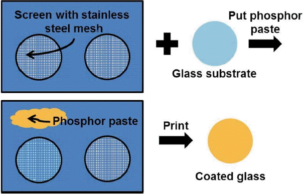
To coat the resultant phosphor paste onto a slide glass (circular glass of 25 mm in diameter), screen printing process was employed. The screen printing process was conducted using a screen (250 mesh) made of stainless steel mesh (Samborn screen) and a rubber squeegee, and the overall process was followed by conventional screen printing procedure. The detailed process is shown in Scheme 1, and the coated sample was dried at 100 °C for 10 min to fix the paste. In general, upon preparation of remote phosphor through the screen printing, overall characteristics of the remote phosphor are varied with types of the screen and compositions of the paste. In this study, a screen without pattern was employed for the mixed type of remote phosphor, while the patterned type of remote phosphor was coated using a patterned screen. All optical properties introduced were measured using an integrating sphere (OPI-100, WITHLIGHT), while the images of surfaces and cross sections were measured by a scanning electron microscope (JSM-7610F, JEOL). Also, X-ray diffraction (XRD) data was measured by an X-ray diffractometer (D/max-2500/PC, Rigaku Corporation).
3. Results and Discussion
In the present study, screen printing process was employed as a method for preparing the remote phosphors. This process is different from the previous production method such as phosphor film or phosphor-in-glass (PiG), and it has advantages of low heat treating temperatures and easy fabrication. For example, characteristics of the resulting objects can be controlled simply by changing formulations of the phosphor paste, and form of the pattern on the remote phosphor can be changed by altering shapes of the screen. In Scheme 1, the method for producing remote phosphors by screen printing process is introduced. As shown in the scheme, the screen printing process was conducted as conventional method which involves coating by dragging from top to bottom using a rubber squeegee after placing the pre-produced phosphor paste. In the present study, two types of remote phosphor were produced with a variety of phosphor formulations and screen shapes, and the optical properties of each remote phosphor were comparatively analyzed.
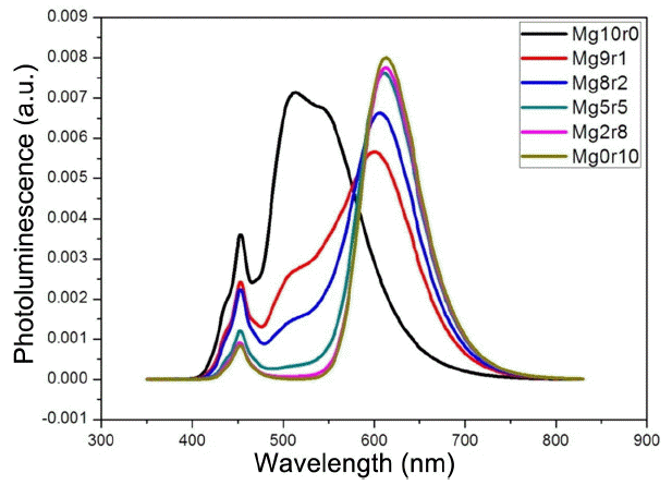
First, the photoluminescence spectrum of a mixed type of remote phosphor is shown in Fig. 1. The mixed type of remote phosphor was fabricated using a mixture of green and red phosphors, and the samples coated using pure green and red colors were also produced and compared for an accurate analysis. For convenience, sample were designated as MgXr (10-X) according to the mixed ratios of red and green phosphors, where X denotes the mass ratio of green phosphor, and (10-X) the mass ratio of red phosphor. In the case of Mg10r0 produced with the pure green phosphor, the maximum photoluminescence intensity was observed at 514 nm, while Mg0r10 produced with the pure red phosphor had the maximum photoluminescence intensity at 613 nm. Considering the graph of Fig. 1, the photoluminescence intensity of red region can be seen to be greatly increased as the ratio of red phosphor is increased. In particular, when Mg10r0 is compared with Mg9r1, the photoluminescence intensity of green region was reduced by 61.9% from 0.007135 to 0.002718 when the red phosphor in Mg0r10 was increased by only 10 wt%, while the intensity of red region was increased by 175% from 0.002134 to 0.008007. Such drastic change is continued until the concentration of red phosphor reaches 50 wt%, above which concentration a severe change in photoluminescence intensities is not observed and a photoluminescence spectrum of a similar form to that of Mg0r10 can be seen to be exhibited.

. PL spectra of the mixed-type remote phosphors. Upto 10 wt% of red phosphor dramatically changed the spectra.
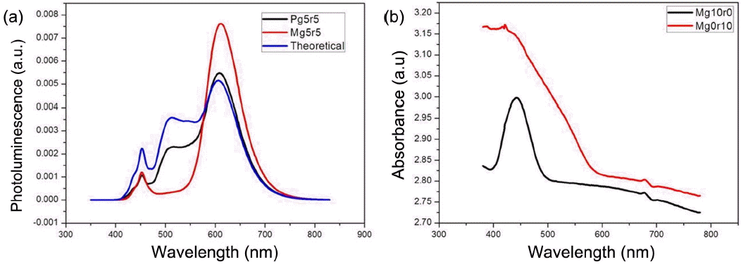
To investigate the interactions between each phosphor, the photoluminescence spectrum of patterned type of remote phosphor was measured. The patterned remote phosphor was designed not to have the overlapped part of phosphors. The patterned type of remote phosphor was prepared by printing the region of red and green phosphors onto the same areas, which was named as Pg5r5. Particularly, to reduce deviations of the light passed through the remote phosphor, the coated area was divided into 16 points where 8 points were coated with green color and the other 8 points with red color. The screen printing process was performed in the same way for both mixed and patterned types of remote phosphor, where the thickness of phosphor layers were observed to be about 38 μm. In Fig. 2(a), the photoluminescence spectrum of Pg5r5 is shown, and that of Mg5r5 is shown together for an accurate comparison. Also, based on the photoluminescence spectrum values of the remote phosphors of pure green and red colors, the photoluminescence spectrum virtually containing green and red phosphor in the ratio of 5 : 5 was calculated and shown together. The photoluminescence spectrum of Pg5r5 is completely different from that of Mg5r5, rather showing the value similar to that for photoluminescence spectrum of Mg9r1. Also, whereas Mg5r5 is greatly different from the calculated theoretical spectrum, Pg5r5 could be seen to have a spectrum at a similar level. This result suggests that photoluminescence spectra on the level proportional to the phosphor concentrations are observed in the case of a patterned type of remote phosphor, while exaggerated red emission in the case of a mixed type. Considering two types of remote phosphor exhibited different photoluminescence spectra, such unique spectrum is attributed to interactions between phosphors, i.e., diversified effects such as difference in light sensitivities inherent to the phosphor, reabsorption phenomenon, difference in filling densities due to a difference in particle forms of green and red phosphors, etc.10,11) In particular, considering the light absorption spectra of green and red phosphors (Fig. 2(b)), the absorption spectrum of red phosphor can be confirmed to appear stronger and wider as compared with that of green phosphor. Hence, it may be determined that the red phosphor not only absorbs the light of blue color source better but also has reabsorption phenomenon occurring by absorbing the light emitted from the green phosphor, directly causing the phenomenon of red color reinforcement. Here, the patterned type of remote phosphor can also be confirmed to show fine differences not in complete agreement with the theoretical photoluminescence spectrum. However, the extent can be smaller than that for the mixed type of remote phosphor, which is a phenomenon occurring due to interaction between red phosphor and green phosphor in the adjacent region since lights emitted from the phosphor are emitted isotropically.11) The phenomenon can also be confirmed in the literature which showed a change in photoluminescence spectra with a change in the form of patterns,12) and a remarkable difference in the photoluminescence spectra can be seen to occur in the case of Pg5r5, since the contact areas between red and green phosphors are relatively large.

(a) Comparison between mixed type, patterned type, and theoretical spectrum which contain 50 wt% of green and 50 wt% of red phosphor. (b) Absorbance spectra of pure green (Mg10r0) and pure red (Mg0r10). The red phosphor exhibited higher and broader absorbance.
To check whether the unique spectrum observed in such mixed type of remote phosphors is caused by chemical reactions between components of the remote phosphors, checking was first made in a morphological aspect. For this purpose, a mutual comparison was made between the remote phosphor coated by using only green (Mg10r0) and red (Mg0r10) pastes and the mixed type (Mg9r1) of remote phosphor. In Figs. 3(a) and (b), scanning electron microscope (SEM) images of Mg10r0 and Mg0r10 are shown, respectively. Two types of phosphors consisted of particles of different forms, where green phosphor was confirmed to have a nearly spherical shape, and red phosphor an angular column form. In the case of Mg9r1 (Fig. 3(c)), round green phosphor and angular red phosphor was found to be uniformly mixed, and reactions such as physical combination by dissolution or destruction of particles can be considered not to have occurred, since external forms of the phosphor were not changed according to the comparison with SEM images of Mg10r0 and Mg0r10. Also, the large difference in size and appearance for green phosphor and red phosphor indicated in SEM images of Fig. 3 may have affected the packing densities, which could have had an effect on the spectrum of mixed phosphor as discussed above.

SEM images of (a) g10r0 (pure green), (b) g9r1 and (c) g0r10 (pure red). Green phosphor had spheroidal shaped particles while red phosphor had rod-like ones.
Also, through X-ray diffraction (XRD) analysis, the status of chemical reaction was additionally checked. For an accurate analysis, XRD data for Mg0r10 and Mg10r0 are shown, respectively, in Figs. 4(b) and (c), and the measured data for Mg9r1 shown in Fig. 4(a). In the case of Mg10r0 and Mg0r10, clear observations of the peaks for LuAG as green phosphor and the peaks for SCASN as red phosphor were confirmed, respectively, as expected. On the other hand, in the graph for measurement of Mg9r1, the diffraction peaks for LuAG as green phosphor were clearly observed, while fine irregularities could be clearly ascribed to red phosphors in the case of SCASN (red circle in Fig. 4). However, other than the peaks for green and red phosphors, absolutely no peaks could be observed, and hence no chemical reactions can be considered to have occurred during the production processes of the mixed type of remote phosphors to the extent of drastically changing the intensities of photoluminescence spectrum.
4. Conclusions
In the present study, screen printing process was performed by using green and red phosphors to produce remote phosphors, and the optical properties were checked by producing two types including mixed type of remote phosphor and patterned type of remote phosphor. In addition, for an accurate comparison, remote phosphors were prepared first by using pure green and red pastes, and theoretical photoluminescence spectra as a function of phosphor contents were calculated using the photoluminescence value of pure green and red remote phosphors. In the case of mixed type of remote phosphors, the intensity of red emission appeared strong for the ratio of red phosphor, and the extent was smaller in the case of patterned type of remote phosphor. This was evidenced through SEM and XRD to be a phenomenon due to interactions between the phosphors rather than a phenomenon due to chemical reactions among the components, with its cause being presumably a combined phenomenon due to various effects such as (1) difference in sensitivities of the light inherent to the phosphor, (2) reabsorption phenomenon, (3) difference in filling densities due to a difference in the particle forms between green phosphor and red phosphor, etc. Such drastic reinforcement phenomenon of red emission is suggested to be capable of supplementing the low thermal stability of red phosphors developed thus far, which warrants further studies.
Acknowledgments
This work was supported by the Industrial Strategic Technology Development program funded by the Ministry of Trade Industry & Energy, Korea, Project No. 10047778.

