


1. Introduction
Solid-oxide fuel cells (SOFCs) are considered as the most promising technology among renewable power generation systems. However, to make them practical and feasible, lowering the operating temperature of fuel cells is a critical challenge for the scientific community. The sluggish oxygen reduction reaction (ORR) kinetics at intermediate temperatures (600-800°C) limit the overall power generation capability.1-6) To address these issues, lanthanum-based transition metal cations containing perovskites have emerged as potential candidates for intermediate-temperature SOFC (IT-SOFC) owing to their mixed electronic-ionic conductivity and high electrocatalytic activity toward the ORR at relatively low temperatures.2,7-10)
Among various perovskite systems utilized as air electrodes for fuel cells such as LSM,11) LSC,12) LSF,13) etc., Sr-doped La1-xSrxCo1-yFeyO3-δ (LSCF) has attracted the most attention along with Gd-doped ceria (GDC)-based composite or barrier layer. A large amount of research has been conducted to study the feasibility and enhance the electrochemical activity of the LSCF cathode.14-29) Initial investigations utilized precious noble metals as a dispersing component to promote the ORR efficiently.15,28,29) However, the high cost and inhomogeneous distribution of the metal catalyst hindered their practical application. Similar to various electrochemical applications, nanostructured electrode materials with small grain size and larger surface area are expected to achieve higher electrocatalytic performance in fuel cells.30-32) Considering this, efforts were made to synthesize nanostructured LSCF by different methods to be utilized as air electrodes for SOFCs. Garcia et al.20) synthesized LSCF powders using a hydrothermal method and obtained a phase-pure product after calcination at 900°C. Fakhrabadi et al.22) demonstrated a low-frequency ultrasound-assisted technique for the synthesis of LSCF, but could not obtain a phase-pure product even after calcination up to 1000°C. Kim et al.24) demonstrated a complex method to synthesize nanocrystalline LSCF using inorganic nanodispersants. They conducted low-temperature sintering at 780°C to retain the small grain size and larger surface area of the air electrode; however, sintering at low temperatures did not provide high stability for long-term operations. In another study, they increased the sintering temperature to 1000°C, but the fabricated cells could only produce a maximum power density of 1.2 W cm−2 at 780°C.26)
Encouraged by the efforts to fabricate nanostructured LSCF as a practical and feasible high-performance cathode for SOFC, we synthesized La0.6Sr0.4Co0.2Fe0.8O3-δ (LSCF6428) powders by a facile solution-combustion route. In particular, we utilized acetylacetone (C5H8O2) in combination with urea (CH4N2O) as fuel, and metal nitrates as oxidizer for the combustion process. The metal cations are expected to first conjugate with the acetylacetonate anion (C5H7O2−) and form metal (La, Sr, Co, Fe)-acetylacetonate complexes, where the oxygen atom in the C5H7O2− anion binds to the metal cation to form a six-membered chelate ring.33,34) Phase-pure LSCF powder was successfully synthesized at calcination temperature of 800°C. The single cell fabricated using the synthesized LSCF cathode displayed a performance enhancement of 112%, from 0.4 to 0.85 W cm−2, even at low-temperature operation (700°C). Finally, electrochemical impedance spectroscopy was employed to analyze the electrochemical behavior of the synthesized cathode. The polarization resistance of the synthesized LSCF6428 cathode was found to be much lower than that of commercial cathode powder. This confirms the enhanced electrochemical activity of the LSCF cathode synthesized by acetylacetone-assisted combustion route.
2. Experimental Procedure
2.1. Powder synthesis
The nanostructured LSCF6428 was synthesized by a new solution-combustion route. First, a metal cation solution (0.1 mol/L) was prepared by dissolving the appropriate amount of La(NO3)3·6H2O, Sr(NO3)2, Fe(NO3)3·9H2O and Co(NO3)3·6H2O (Alfa Aesar) in a mixture of de-ionized water and ethanol. Then, 2 g of urea and 50 ml acetylacetone (Sigma Aldrich) were added to the solution prior to heating at 120°C. After 1 h, the temperature was raised to 350°C, above the autoignition temperature of acetylacetone (340°C). This led to the rapid evaporation of residual solvents and decomposition of urea with the exothermic release of energy. The solution became very thick and ignited with glowing flints. The combustion continued for approximately 1 min and generated a highly porous foamy ash at the end. The ash was first ground and subsequently calcined at 800°C for 6 h to obtain the LSCF nanopowders.
2.2. Fuel cell fabrication
The typical anode-supported multilayered fuel cell was fabricated similar to previous reports.35) Briefly, the cell consisted of NiO-YSZ support coated with a thin functional layer (FL), YSZ electrolyte, barrier layer, and the synthesized LSCF6428 cathode (air electrode) layer. First, NiO-YSZ fuel-electrode support was fabricated by tape-casting and presintered at 900°C for 2 h. A thin NiO-YSZ functional layer was coated over it by the dip-coating method and heat-treated at 800°C for 2 h to enhance the electrocatalytic oxidation of fuel at the electrode/electrolyte interface. Similarly, a YSZ electrolyte layer was coated by dip-coating, and the whole assembly was co-sintered at 1450°C for 5 h. To prevent direct contact between the Sr-doped LSCF6428 cathode and YSZ electrolyte, a 10GDC barrier layer was coated onto the YSZ electrolyte by screen-printing before heat treatment at 1250°C for 2 h. Finally, the synthesized LSCF6428 powder was mixed with an organic binder (Texanol-based vehicle, ESL ElectroScience, United States) and screen-printed over the 10GDC barrier layer followed by sintering at 1100°C for 1 h to form the air electrode of the cell. To carry out a comparative study, commercial LSCF6428 powder (Sigma Aldrich, CAS-704288) was utilized as the air electrode of a reference cell fabricated similar to the abovementioned process.
2.3. Physical and electrochemical characterizations
The crystal phase structures of the synthesized and commercial powders were analyzed by powder X-ray diffraction technique using Rigaku D/MAX Ultima III diffractometer (Japan) by Cu Kα characteristic radiation (λ = 1.54056 Å). The microstructural and morphological study was carried out by a field-emission scanning electron microscope (Hitachi High-Tech S-4700, Japan) equipped with energy-dispersive X-ray (EDX) analysis facility. Thermogravimetry analysis-differential scanning calorimetry (TGA-DSC) was performed over a thermal analyzer (SDT Q600, TA Instruments, United Kingdom) from room temperature to 850°C (5°C/min) in air atmosphere. The surface area and average pore diameter of the synthesized LSCF were determined by the ASAP® 2020 Plus: Accelerated Surface Area and Porosimetry System (Micromeritics Instrument Corporation, United States).
The fuel cell performance and electrochemical properties were measured in a laboratory-made electrode-separated compartment test station. The cell with an active electrode area of 0.5 cm2 was gas-seal affixed by Ceramabond (Aremco, United States). A Ni-paste with a Pt gauge (100 mesh) was used as the current collector for the fuel electrode. Similarly, a platinum paste (Heraeus 6926, Germany) with Pt gauge (100 mesh) was used for current collection from the air electrode. The fuel electrode was supplied with humified hydrogen (H2, 6% RH), while the air electrode was supplied with synthetic unhumidified air; the total flow rate at each electrode was fixed at 250 sccm using mass flow controllers (Atovac, Republic of Korea). Electrochemical properties such as current-voltage characteristics (I-V) and electrochemical impedance spectroscopy (EIS) measurements were obtained using Gamry Reference 3000 Potentiostat/Galvanostat/ZRA (Gamry Instruments, United States). The ac impedance was measured at open-circuit potentials (OCP) in the frequency range of 0.1 Hz to 1 MHz. I-V curves were measured in the potential range of OCP to 0.6 V.
3. Results and Discussion
3.1. Physical properties
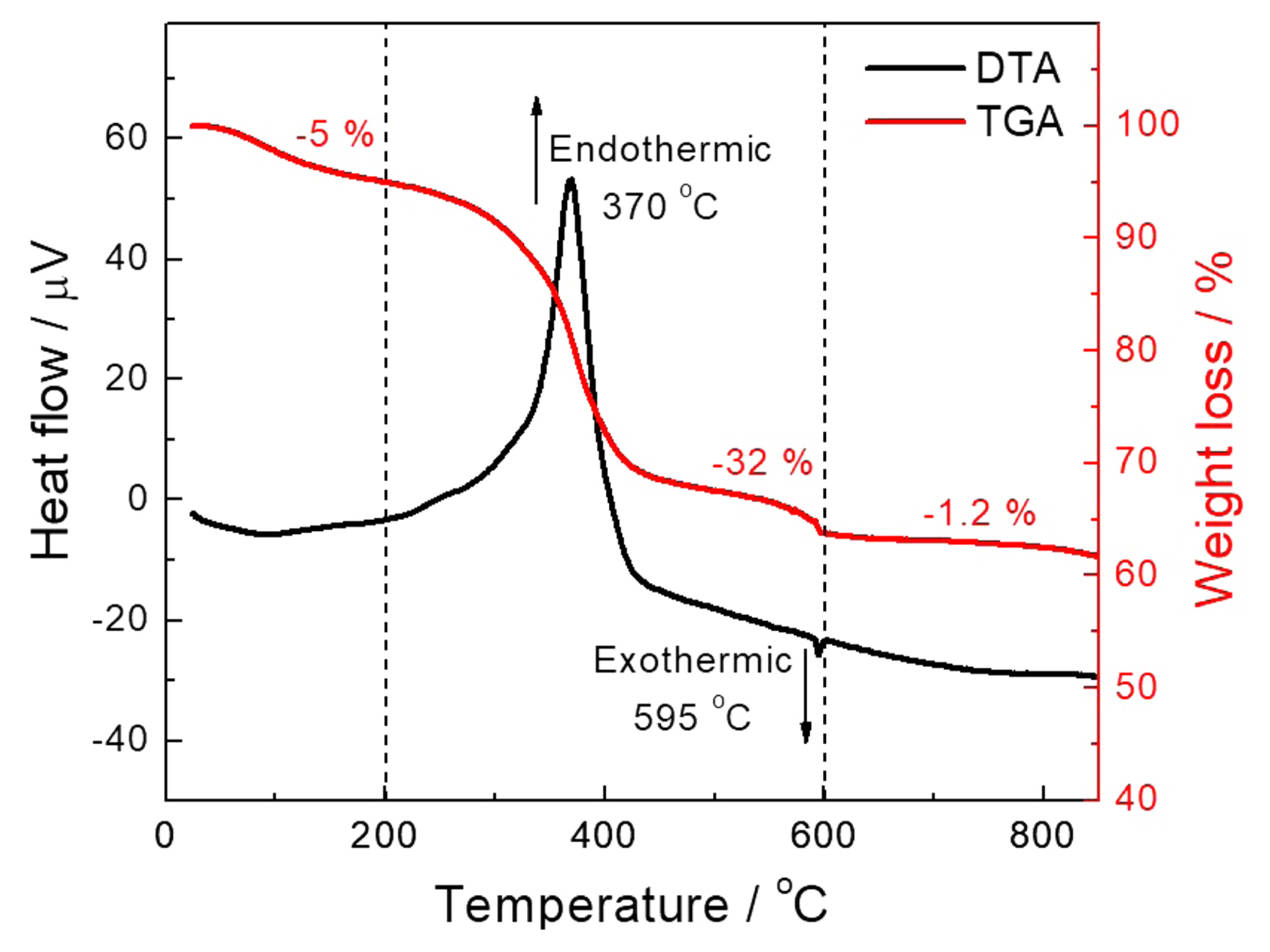
Figure 1 shows the TGA/DSC curves of the LSCF powder before calcination. The total thermal analysis can be classified into three zones from 25 to 850°C. The initial weight loss of approximately 5% observed until 200°C could be attributed to the loss of adsorbed and crystallized water. Then, a major weight loss of approximately 28% was observed between 200 and 600°C, attributed to the thermal decomposition of residual metal acetonate-urea complexes. Finally, a small weight loss of approximately 1.2% was observed at 600-800°C, attributed to phase formation. The TGA results were well supported by DSC measurements, showing a major endothermic peak at ~ 370°C, which corresponds to the energy gained by the system for the decomposition of metal-organic complexes. A small exothermic peak at ~ 595°C corresponds to the heat of crystallization of the perovskite phase.
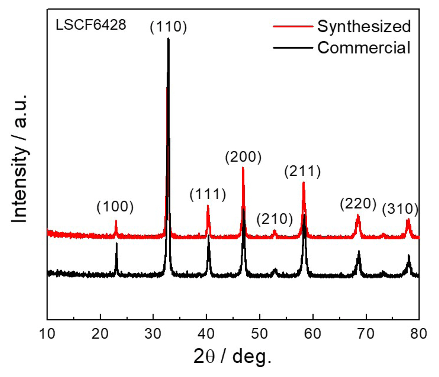
Figure 2 shows the XRD pattern of the synthesized LSCF6428 powders calcined at 800°C along with the commercial LSCF6428 powder. The synthesized powder showed a diffraction pattern that closely matched that of commercial powder with a rhombohedral lattice structure (JCPDS #49-0284, space group: R-3c, space group number: 167) at room temperature, similar to the reports in literature.36) All the peaks were assigned to their corresponding diffraction planes. The synthesized powder showed crystallite size comparable to the commercial LSCF6428, ~ 25 nm determined through Scherrer’s equation. No additional peaks due to impure/secondary phases were observed.
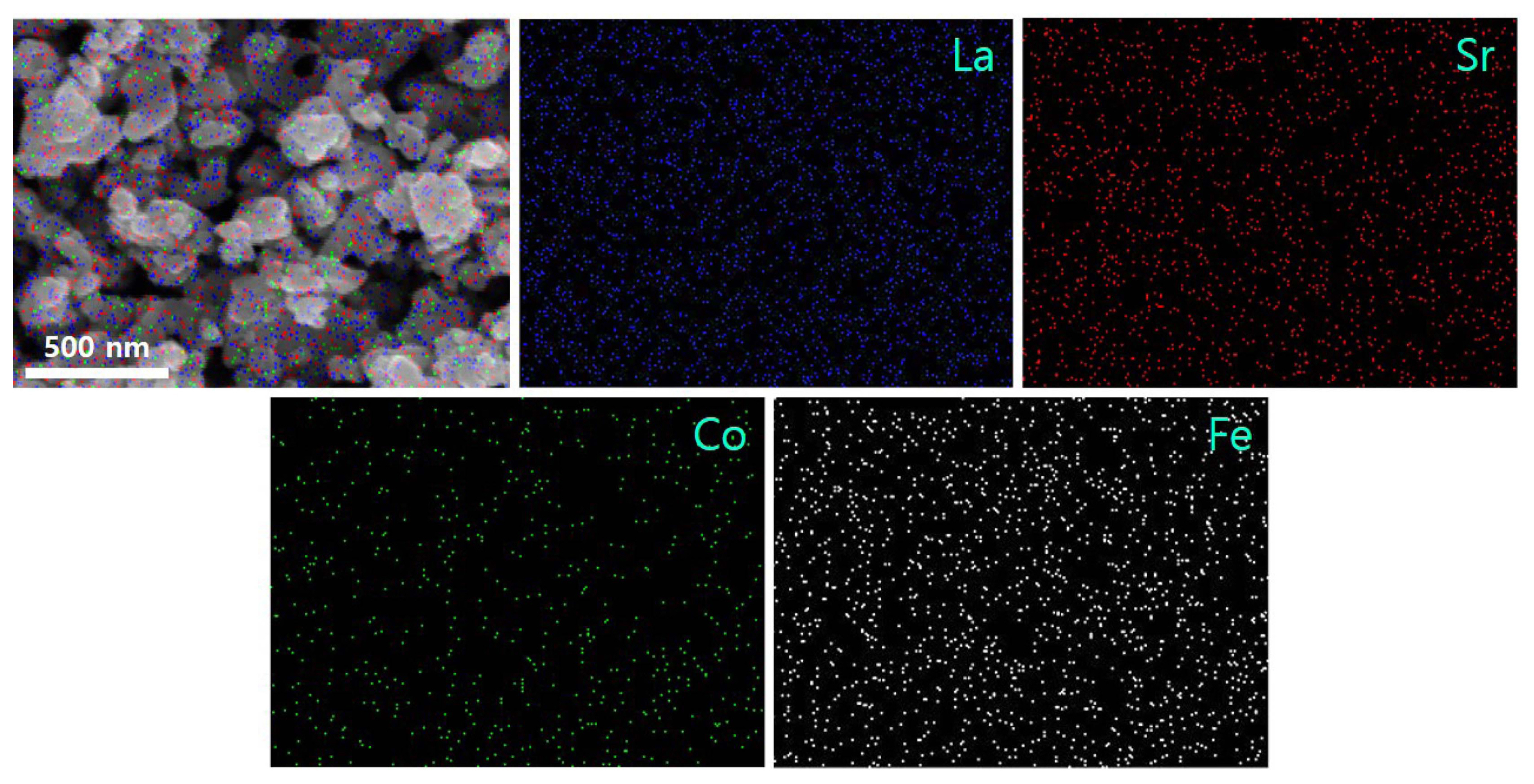
The morphology observed in Fig. 3 showed that the commercial powder consists of large micrometric particles, typically in the size range 0.7-1.1 μm. In contrast, the powder synthesized by the new acetylacetone-assisted combustion route is comprised of fine-grained nanoparticles in the size range 50-200 nm. Moreover, the Brunauer-Emmett-Teller surface area was found to be ~ 12.8 m2g−1 (average pore diameter = 24.48 nm), almost 200% of the average surface area of commercial LSCF6428 powder. Nanopowders typically show higher electrocatalytic activity compared with bulk powders owing to their larger surface area and better gas-diffusion pathways;30-32) therefore, the synthesized LSCF6428 cathode is expected to enhance the ORR and improve fuel cell performance. The elemental distribution in the synthesized LSCF was evaluated by EDX spectroscopy. Fig. 4 shows the elemental distribution of elements such as La, Sr, Co, and Fe. All the elements were found to be homogeneously dispersed in the powder, which suggests that the acetylacetone-assisted synthesis route is highly suitable for the synthesis of multi-cation systems.
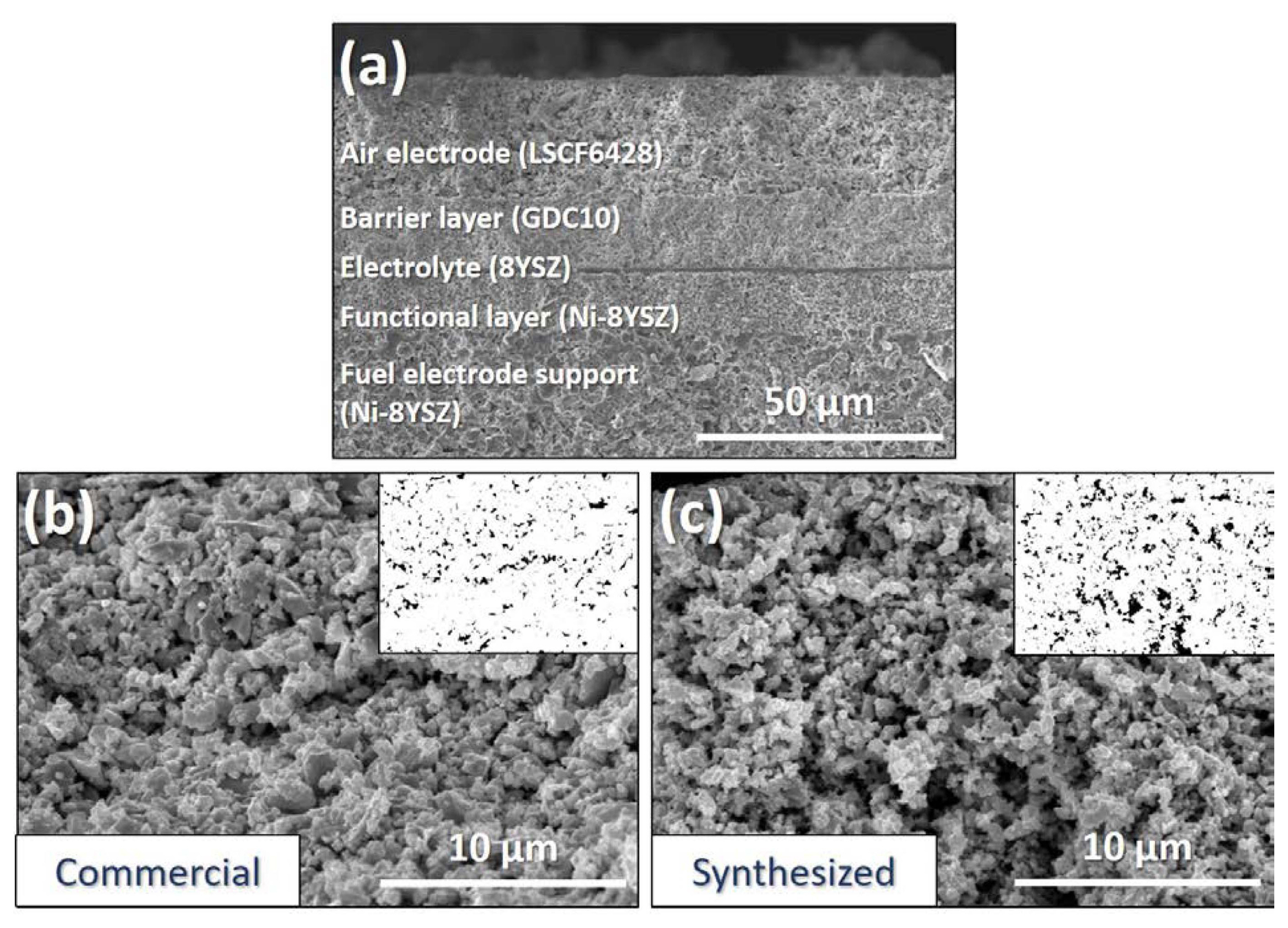
The surface morphology of the air electrode and fractured cross-sectional morphology of the fabricated fuel cells are shown in Fig. 5. The layered-cell structure in Fig. 5(a) consists of four layers: a fully-reduced fuel electrode support (Ni-8YSZ) of ~ 400 μm coated with a FL (Ni-8YSZ) of ~ 10 μm; a dense electrolyte layer (8YSZ) of ~ 1 μm; a barrier layer (10GDC) of ~ 12-15 μm; and a porous air-electrode layer (synthesized LSCF) of 20-25 μm. Both cells were fabricated in same manner and each layer thickness was almost identical. Figs. 5(b) and 5(c) show the surface morphology of the air-electrode layer sintered at 1100°C for the commercial and synthesized LSCF, respectively. It was found that the electrode layer with the synthesized powder provides much higher porosity (10.38%) compared with the commercialized one (5.08%). The increase in the porosity is expected to improve gas diffusion up to the triple phase boundary (TPB), leading to enhanced ORR kinetics and better fuel cell performance.
3.2. Electrochemical properties
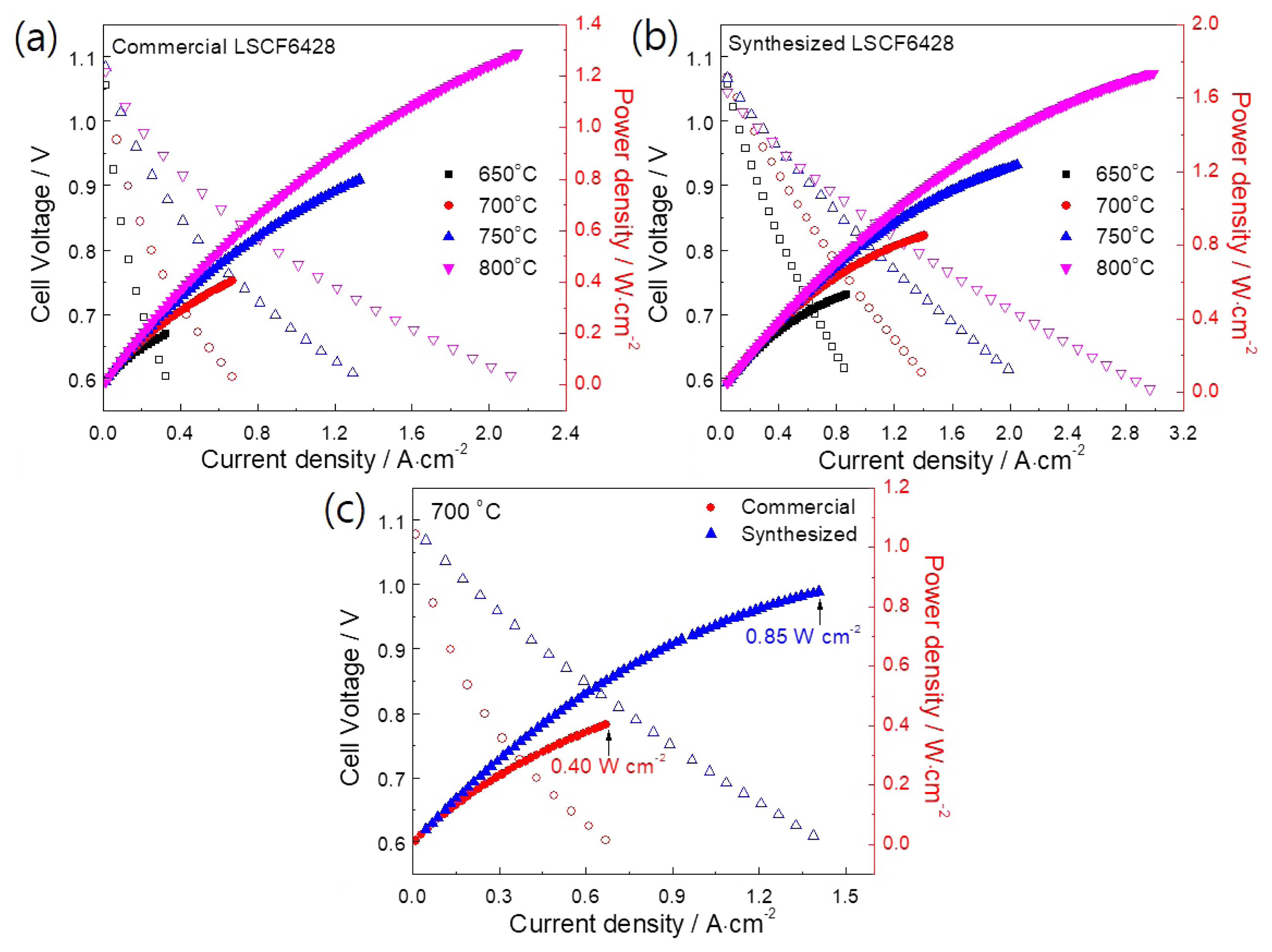
Fuel cell performance measurements were conducted in the operating temperature range 650-800°C. The steady-state I-V curves are shown in Fig. 6. The OCP was found to be in the range 1.05-1.08 V and 1.04-1.07 V for the cells consisting of commercial and synthesized LSCF6428 air electrodes, respectively. A gradual increase in power densities was observed with an increase in operating temperature. The maximum power densities (Table 1) obtained from the commercial LSCF air electrodes (Fig. 6(a)) were 0.19, 0.40, 0.8, and 1.29 W·cm−2 at 650, 700, 750, and 800°C, respectively. In contrast, the cell with the synthesized LSCF air electrode (Fig. 6(b) ) had maximum power densities of 0.53, 0.85, 1.24, and 1.74 W·cm−2 at 650, 700, 750, and 800°C, respectively; much higher than those of the commercial cathode powder. The increase in performance could be attributed to the increased TPB areas and advanced electrocatalytic activity of the synthesized nanosized LSCF6428 air electrode. Since long-term operation at high temperatures could result in grain coarsening and decreased TPB areas, a relatively low operating temperature could be favorable. Therefore, Fig. 6(c) presents a comparative analysis of cell performance at 700°C. It was determined that the fuel cell performance was increased by more than 112%, from 0.4 to 0.85 W cm−2, by utilizing the acetylacetone-assisted combustion synthesized LSCF powder.
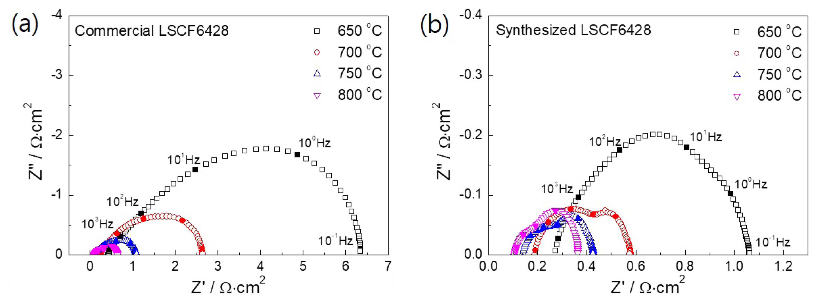
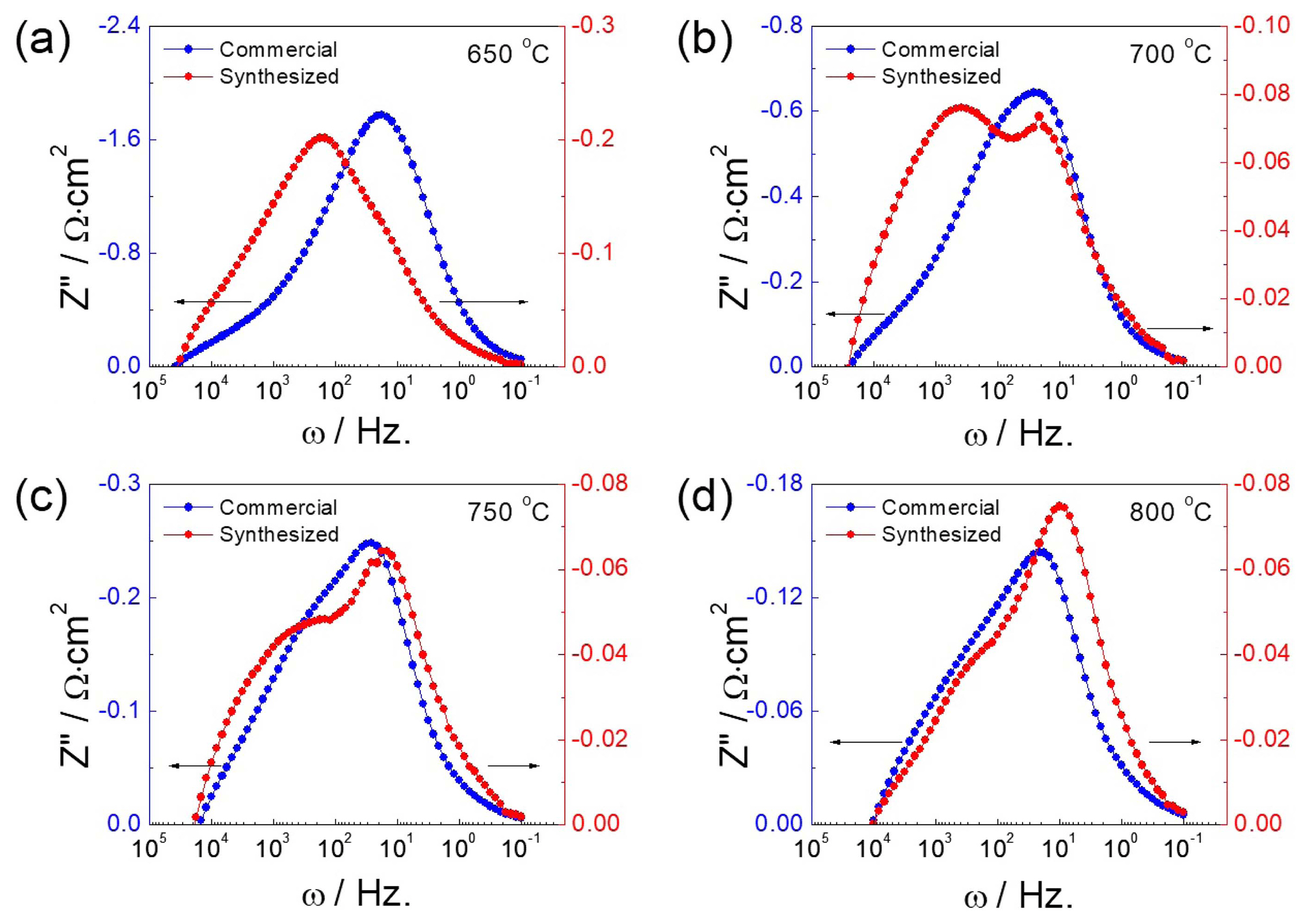
EIS was further employed to perform insight analysis on the enhanced fuel cell performance caused by the air electrode. Fig. 7 represents the Nyquist plot of the impedance spectra showing a semicircular arc consisting of possible multiple contributions from various fuel cell components. It was found that the impedance spectra tend to contract inwards with the increase in operating temperature. The high-frequency intercept on the real axis associated with electrolyte contributions was comparable for both fuel cells. In contrast, the low-frequency impedance spectra of the fuel cell could be associated with several relaxation processes including adsorption-desorption, gas/ionic diffusion, and electrochemical reactions with multiple intermediate steps for fuel oxidation and oxygen reduction.37-38) Compared with the fuel cell with commercial LSCF (Fig. 7(a)), the low-frequency impedance spectra of the fuel cell with synthesized LSCF air electrode (Fig. 7(b)) intercepted the real axis at much lower values, which suggests an overall decrease in the impedance of the fuel cell. In Fig. 8, the imaginary component of the impedance spectra is shown as a function of ac frequency. A convoluted response of polarization resistance due to multiple electrode processes was observed as a peak at frequency of approximately 10 Hz. The decrease in peak intensity with the increase in operating temperature from 650 to 800°C reflects the advanced reaction kinetics at higher operating temperature for both electrodes. For the synthesized LSCF cathode, the curves also show a shift in the peak center over the frequency range, suggesting a transition in the rate-determining process as a function of operating temperature. Moreover, the polarization resistance of the synthesized LSCF cathode was much lower than that of the commercial cathode powder at each operating temperature, which confirms the enhanced electrochemical activity of the LSCF cathode synthesized by acetylacetone-assisted combustion route.
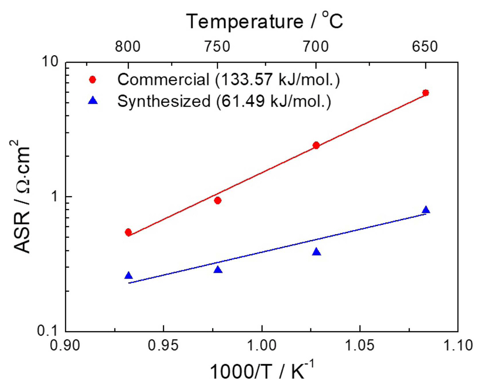
The area-specific resistance (ASR) was determined by considering the quantitative difference between the high- and low-frequency intercepts on the real axis of the impedance spectra in the Nyquist plot (Fig. 7). Fig. 9 corresponds to the ASR of the fuel cell with commercial and synthesized LSCF air electrodes as a function of operating temperature. As shown in Table 2, the cell consisting of commercial LSCF air electrode had ASR values of 5.91, 2.4, 0.97, and 0.93 Ω·cm2, while the synthesized LSCF had ASR values of 0.79, 0.38, 0.28, and 0.25 Ω·cm2 at 650, 700, 750, and 800°C, respectively. A significant reduction in the ASR of the synthesized LSCF could lead to high current-drawing capacity from the fuel cell. Furthermore, the activation energy of the synthesized LSCF was calculated to be 61.49 kJ/mol, much lower than 133.57 kJ/mol determined for the commercial LSCF cathodes. This indicates the considerable enhancement of ORR kinetics under the same thermodynamic conditions.
4. Conclusions
LSCF6428 was successfully synthesized through an acetylacetone-assisted combustion route and utilized as the air electrode (cathode) of IT-SOFCs. The synthesized powder exhibited a high degree of crystallinity and retained the nanostructured morphology. The electrode layer comprising nanostructured LSCF displayed much higher porosity than that of commercial LSCF cathode, even after high-temperature sintering at 1100°C. The maximum power density of the single cell fabricated with the synthesized LSCF6428 air electrode increased by 112%, from 0.4 to 0.85 W·cm−2, at 700°C. EIS was utilized to analyze the performance enhancement of the fuel cell. It was found that the polarization resistance of the synthesized LSCF6428 cathode was much lower than that of the commercial cathode powder at each operating temperature. The fuel cell with nanostructured LSCF cathode displayed much lower ASR compared with the commercial powder. The significant reduction in activation energy from 133.5 to 61.5 kJ/mol resulted in the enhanced ORR kinetics and improved performance.