


1. Introduction
Ceramics with a tailored porous network have attracted much attention for the use in various applications and many studies are being performed to identify suitable fabrication technique for porous structures with reasonable strength. Among the many porous ceramics in use, SiC is one of the best candidates owing to its high strength, excellent corrosion and high temperature resistance.1-3) Generally, the methods for fabricating porous SiC can be classified as recrystallization,4) sintering,5) reaction bonding,6) oxidation bonding,7) and glass bonding,8) depending on the mechanism of neck formation. The temperature required for these processes decreases gradually from 1800 to 1000°C when the process proceeds from recrystallization towards glass bonding. Although glass bonding requires the lowest processing temperature, the leaching of alkaline elements under extreme pH limits its application.9) Therefore, oxidation bonding might be a viable route to prepare a porous SiC at relatively low processing temperatures of 1100-1500°C, while maintaining the leaching resistance at the same time.
Silica (SiO2) or mullite (2Al2O3SiO2 or 3Al2O32SiO2) has been used traditionally to form a neck between the SiC grains.10) Compared to silica, mullite has a better oxidation resistance and high temperature stability because of its lower oxygen diffusion coefficient and higher melting point.11,12) In addition, the similar thermal expansion coefficients of mullite (4.5 × 10⁻⁶/K) to SiC (4.7 × 10⁻⁶/K) results in excellent thermal shock resistance as well as high strength of the porous SiC.13,14)
Instead of the direct addition of mullite to SiC, an alternative Al-source can also be used to form a mullite bond by a reaction between Al2O3 and SiO2 on the SiC surface.15) A range of Al sources, such as Al powder16), Al2O3 17), and bauxite 18), have been evaluated for the fabrication of mullite-bonded porous SiC. Kumar et al.19) examined the effects of different Al sources on the strength of a porous SiC body, where the strength was found to be dependent on the type of Al-source employed. This is because the Al-source material with high mechanical properties increases the overall strength of the porous SiC.20)
In this aspect, one possible filler material is the Ti3AlC2 MAX phase, which decomposes to Al2O3 and TiO2 at high temperatures in the presence of oxygen.21,22) The formation of Al2O3 upon the oxidation of Ti3AlC2 may assist in the formation of a mullite neck by a reaction with SiO2 on the SiC particles, while the high mechanical properties of the Ti3AlC2 phase can still be maintained beneath the oxide layer, even after prolonged thermal treatment, providing sufficient strength to the porous SiC. Indeed, Ti3AlC2 has a higher fracture toughness (9.1 MPa·m1/2) than Al2O3 (4.5 MPa·m1/2).14,23) Based on these backgrounds, this study examined the feasibility of Ti3AlC2 MAX phase for the first time as an alternative Al-source for the neck formation of porous SiC despite its high cost.
2. Experimental Procedures
2.1. Starting materials and the fabrication of porous SiC tube
The starting materials were β-SiC (> 99%, D50=10 μm, Alfa Aesar, U.K.) and Ti3AlC2 (> 98%, D50=32 μm, Beijing Jinhezni Materials, China); tapioca starch (Bangkok Inter Food, Thailand) was used as a binder. Because the mixture of β-SiC and Ti3AlC2 compact revealed fracture due to the high volumetric expansion of Ti3AlC2 upon oxidation, based on preliminary test, the as-received Ti3AlC2 was partially oxidized at 1200°C for 30 min prior to use.
The mixture of 60 wt.% SiC + 25 wt.% heat-treated Ti3AlC2 + 15 wt.% tapioca starch was formed into a thick paste for extrusion after adding 40 wt.% de-ionized water by pugging using a mortar and pestle. A hollow tube with an outer diameter of 17 mm and a wall thickness of 2.5 mm was fabricated by extrusion, which was heat-treated at 500°C for 2 h for binder burn-out followed by sintering at 1100, 1200, 1300, and 1400°C for 3 h in air.
To deposit a thin filter layer with fine pores at the outer surface of the SiC porous tube, an aqueous α-SiC (> 99%, D50=0.5 μm, H. C. Starck, Germany) slurry with Ti3AlC2 was prepared by ball milling after adding an acrylic binder (WB 4101, Polymer Innovations, U.S.A.) and dispersant (Cerasperse 5468CF, SANNOPCO, Korea). Prior to use, Ti3AlC2 was milled using a high-energy mill (MiniCer, Netzsch, Germany) for 1 h at a rotor speed of 3,000 rpm with 0.45 mm ZrO2 beads, which revealed a mean particle size of 0.15 μm. The slurry contained 1 and 10 wt.% of dispersant and binder, respectively, along with 600 wt.% deionized water with respect to the ceramic powder. After forming a filter layer by dip coating for the sintered tube for 1 min, the tube was dried and heat-treated at 1200°C for 1 hr.
Phase analysis and microstructural characterization of the samples were performed by X-ray diffraction (XRD, PANalytical, X’pert-PRO MPD, U.K. using 40 kV, 30 mA and Cu Kα radiation) and scanning electron microscopy (SEM Hitachi S-4800, Japan) coupled with energy dispersive spectroscopy (EDS, Horiba EX-250, Japan). The XRD patterns were used to quantify the weight fractions of the resulting phases using a Rietveld simulation (HighScore Plus, Malvern PANalytical). The density of the samples was measured using the Archimedes method and compared with the theoretical densities of the samples calculated using the linear rule of mixtures. In addition, the pore size and distribution of the samples were characterized quantitatively using a mercury intrusion method (ASAP 2460, Micromeritics, U.S.A.). The strength of the sintered tube was measured using an O-ring test, according to the JIS-Z-2507 standard. 24) At least 3 samples were measured for each condition to ensure reproducibility. Moreover, to evaluate the long-term stability of the porous SiC tubes, their mechanical strength was evaluated after exposure for 500 h to the pH = 3 and 11 solutions.
3. Results and Discussion
When heat-treated at high temperatures in the presence of oxygen, Ti3AlC2 undergoes massive volumetric expansion upon oxidation, accompanied by an approximately 40% weight gain.25) As a result, the sample prepared using 60 wt.% SiC + 25 wt.% as-received Ti3AlC2 + 15 wt.% tapioca starch fractured after heat treatment at ≥ 1000°C in air. Therefore, the as-received Ti3AlC2 powder was partially oxidized at 1200°C for 30 min prior to use to prevent fracturing of the tube. Table 1 lists the phase evolution calculated by a Rietveld simulation using the XRD pattern upon the heat treatment for pure Ti3AlC2 powder at various temperatures for 30 min in air. Ti3AlC2 was maintained until 400°C but started to decompose to TiO2 and Al2O3 at 600°C, according to the following reaction equation (1)26):
At 1400°C, Al2TiO5 was generated by a reaction of Al2O3 and TiO2, as shown below:
According to Table 1, anatase TiO2 was observed at 600-800°C due to the decomposition of Ti3AlC2, which was transformed to a high temperature-stable rutile phase at ≥ 1000°C. Based on the result, Ti3AlC2 heat-treated at 1200°C was used for further experiment to maximize the amount of Al2O3 for mullite formation, where 28 wt.% of the initial Ti3AlC2 was still maintained. According to the literature, Al2O3 begins to form mullite below 1000°C due to a reaction with SiO2, while the decomposition of Al2TiO5 is difficult even at 1100°C.27,28)
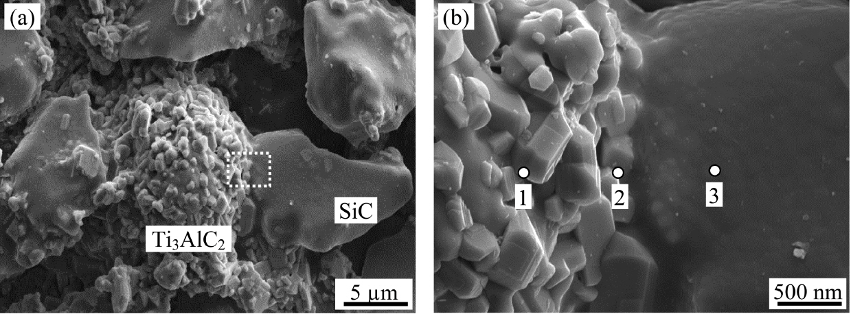
Figure 1 shows the fractured surface morphology of the sample after heat treatment at 1200°C for 3 h in air. Coarse SiC particles are connected by Ti3AlC2 along with the presence of pores between the particles, as shown in Fig. 1(a). Fig. 1(b) shows a magnified image of the area marked with the white rectangle in Fig. 1(a). Although the as-received Ti3AlC2 has a layered structure, the surface of Ti3AlC2 shows many small crystals after heat treatment, indicating the formation of TiO2 and A12O3, according to the reaction equation (1). Based on the EDS results in Table 2 for the points shown in Fig. 1(b), the coexistence of Al2O3, TiO2, and Ti3AlC2 can be estimated for point 1 from the relative ratio of the elements and the presence of carbon. Although the coarse particle is SiC, a significant amount of oxygen was detected for point 3 because of the formation of SiO2 upon oxidation. On the other hand, Si, O, and Al were observed in the absence of Ti at point 2, which is the boundary between the SiC and Ti3AlC2, implying the formation of mullite phase.
Because crystalline Ti3AlC2 has a layered structure with an edge-sharing Ti6C octahedron along the c-axis,29) the oxidation of Ti and Al is relatively easy owing to the rapid oxygen diffusion path through the open structure between the layers. Al has a higher oxidation tendency than Ti based on the Gibbs formation free energy for the oxidation of Al and Ti, which is −401.5 and −227.0 kJ at 1200°C, respectively. On the other hand, the existence of a much larger amount of TiO2 than Al2O3 is possible according to the stoichiometry in reaction equation (1), as shown in Table 1, because the growth rate of TiO2 is five orders of magnitude faster than that of Al2O3 at this temperature.30)
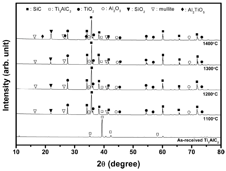
Figure 2 shows the XRD patterns of the Ti3AlC2-added porous SiC after heat treatment at each temperature for 3 h in air. The presence of Al2O3, TiO2, Ti3AlC2, and mullite was detected at all temperatures, while Al2TiO5 was detected only after the 1400°C treatment, which agrees to the phase evolution shown in Table 1. The traces of mullite phase can be found even at 1100°C, while the relative amount of SiO2 increases with increasing temperature owing to the enhanced oxidation of SiC. In addition, a small amount of Ti3AlC2 was also detected, suggesting that the Ti3AlC2 particles were not fully decomposed even after heat treatment at 1400°C.
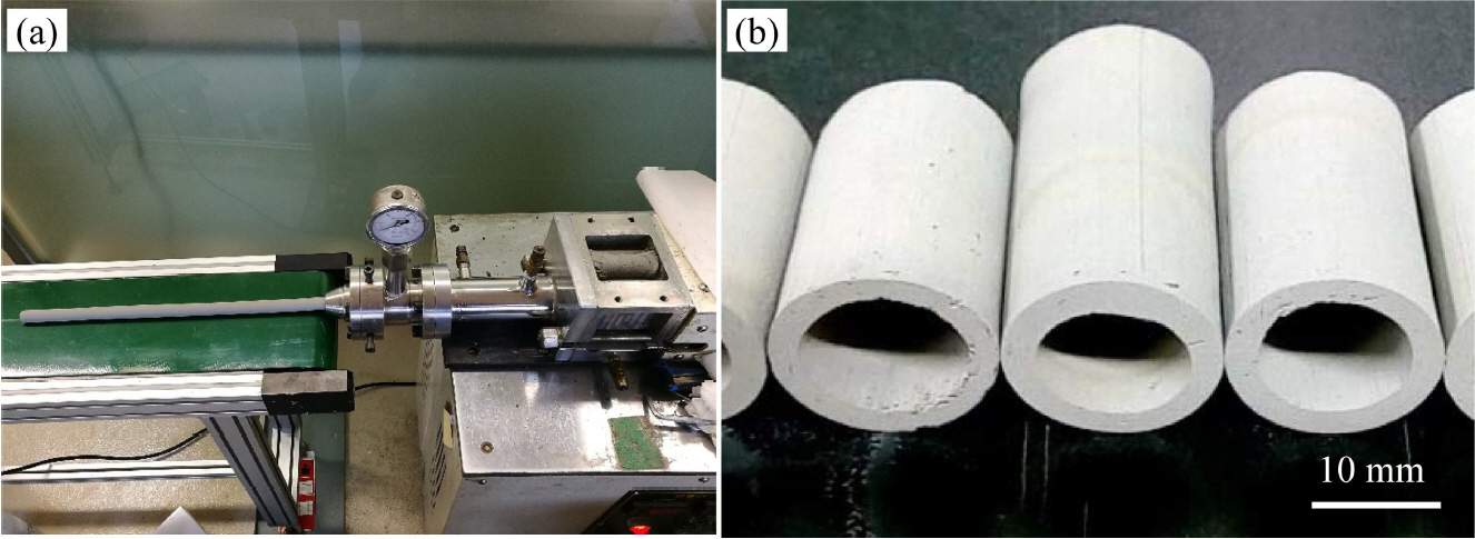
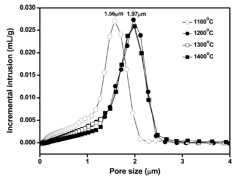
When the thick paste was extruded using the equipment shown in Fig. 3(a), a tubular shape could be fabricated without notable defects, indicating the effectiveness of aqueous tapioca starch as a binder and lubricant. Fig. 3(b) presents the Ti3AlC2-added porous SiC tube after heat treatment at 1400°C, which does not show deformation of tubular shape after the high temperature treatment. According to the pore size distribution results shown in Fig. 4, the sample heat-treated at 1100°C showed a modal pore size of 1.56 μm, while those treated at 1200, 1300, and 1400°C showed a larger modal size of 1.97 μm, regardless of the temperature change. On the other hand, the frequency of fine pores smaller than 1.5 μm decreased with the increasing temperature owing to the enhanced particle coarsening, which also accompanies pore coarsening.
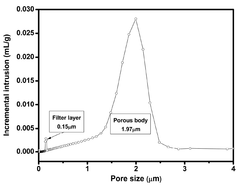
A porous membrane for filter application generally uses an asymmetric design, which is composed of a supporting layer containing large pores and a filter layer containing small pores.31,32) The supporting layer should be strong enough to maintain the body under high pressure, while the filter layer consists of fine pores to separate the contaminants effectively by physical separation. At the same time, the filter layer should be thin enough to maximize the permeability of the medium. Fig. 5 shows a SEM image of the Ti3AlC2-added porous SiC tube heat-treated at 1400°C after coating a fine filter layer by dip coating 2 times followed by heat treatment at 1200°C. The supporting layer prepared using coarse SiC particles showed large pores, while the upper filter layer formed using a fine SiC and Ti3AlC2 revealed a porous microstructure with very fine pores. When dip coating was performed 1-, 2- and 3-times, the thickness of filter layer was 20, 28 and 36 μm, respectively, implying possible controlling of the filter layer thickness. When the pore size distribution of this sample was analyzed, very fine pores, 0.15 μm in size, were detected from this filter layer in addition to large pores with 1.97 μm for the supporting layer treated at 1400°C, as shown in Fig. 6.
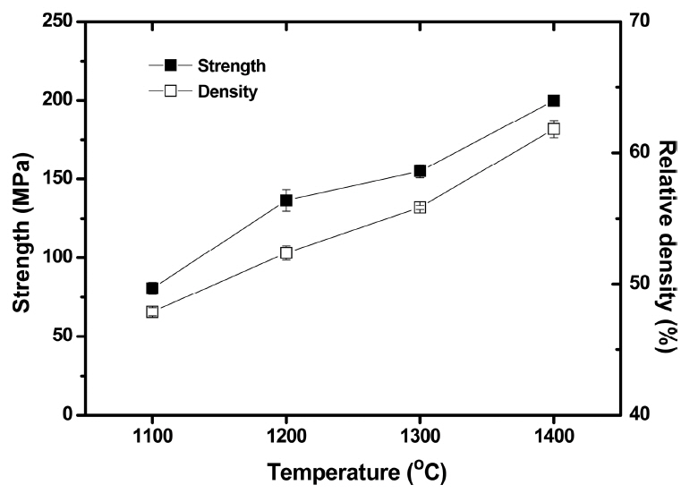
Figure 7 shows the mechanical strength based on an O-ring test and relative density of the Ti3AlC2-added porous SiC tubes as a function of the heat treatment temperature. The relative density of the samples increased from 48 to 62%, whereas the mechanical strength also increased from 80 to 200 MPa with increasing temperature from 1100 to 1400°C. The overall properties of porous SiC using Ti3AlC2 as a bonding material in this study were compared with those using Al2O3 in Table 3. The previous study by Zhou et al. used 3 wt.% Al2O3 as a bonding material and sintered at 1800-1900°C in an Ar atmosphere, where the formation of a mullite neck could not be observed owing to the inert atmosphere. 34) Although the preparation conditions between the two studies were different, this study revealed a much higher mechanical strength despite the similar density, which was attributed to the rigid mullite bonding along with the retained Ti3AlC2 with high mechanical properties beneath the mullite neck. Moreover, 99 and 97% of the mechanical strength was retained after exposure to the pH = 3 and 11 solutions for 500 h, indicating stability of the mullite-based necking materials under highly corrosive conditions. However, the effect of decomposed TiO2 on the mechanical properties of porous body needs further study even though it is estimated that the TiO2 formed does not react with Al2O3 or Ti3AlC2 below 1400°C because a significant amount of TiO2 remained after heat treatment at various temperatures, as shown in Fig. 2.
4. Conclusions
This paper reported the feasibility of Ti3AlC2 as an Al source for the fabrication of porous SiC tubes by oxidation bonding. Pre-heat treatment of the as-received Ti3AlC2 at 1200°C was required to prevent fracturing of the porous tube by minimizing the volume expansion upon oxidation. The decomposition of Ti3AlC2 to TiO2 and Al2O3 starts at 600°C, where mullite bonding among the SiC particles forms at ≥1000°C by a reaction between Al2O3 and SiO2 on the SiC. Owing to the rigid necking by mullite and the retained Ti3AlC2 beneath the oxidation bonding after heat treatment at 1100-1400°C in air, the porous SiC tube exhibited a much higher mechanical strength compared to the porous SiC tube formed with an Al2O3 filler. Moreover, the thin filter layer containing fine pores formed by the dip coating method revealed firm attachment to the supporting layer, where the thickness could be controlled by adjusting the coating parameters. Overall, this report shows that the use of Ti3AlC2 for the fabrication of porous SiC results in high mechanical properties due to the formation of strong mullite neck and the presence of Ti3AlC2.