1. Introduction
Transition metal oxides (TMOs) are interesting functional materials owing to their unique physical and chemical properties; these properties give them a variety of functional applications.1,2) Among the transition metal oxides, copper (Cu)-based oxides, including cuprous (Cu2O) and cupric (CuO) oxides, have attracted increasing attention as promising candidates for usage in lithium-ion batteries (LIBs),2-6) solar cells,7) supercapacitors,8) gas-sensors,9) bio-sensors,10) and catalysts11) owing to their unique properties as a p-type semiconductor with a low band-gap energy, high optical absorption, and high catalytic activity. Furthermore, they are non-toxic, inexpensive, and can be easily produced. 3-11) In particular, the cuprous (Cu2O, 375 mAh g−1 2)) and cupric (CuO, 674 mAh g−1 2)) oxides have recently been considered as a potential alternative anode to replace graphite (LiC6, 372 mAh g−1 2)) in LIBs due to their decent capacity.2-6) However, high-capacity anode materials, including Cu2O and CuO, are known to suffer from poor cyclability and subsequent low capacity caused by the severe volume change that they undergo while charging and discharging, in addition to having low electronic conductivity.5,6) To solve these limitations, various electrode structure modifications, such as nanoflower,3) nanosheet,4) nanorod,5) and nanoflake, 6) have been attempted, resulting in the considerable improvement of the electrochemical performance of LIBs.2-6)
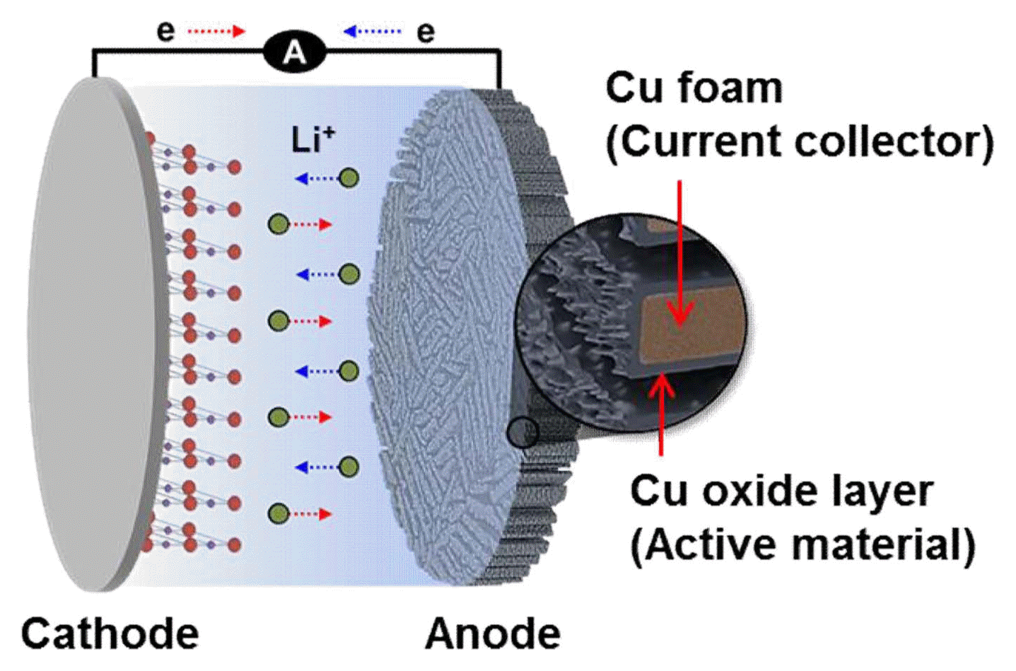
Herein, we designed and fabricated a porous CuO/Cu2O/Cu anode with microscale wall pores and corrugated wall pores (dual pore structure) for potential use in LIBs (Fig. 1). This anode architecture consists of microporous Cu foam as an anode current collector and a nanowire-like Cu oxide layer thermally grown on the Cu foam as an anode active material. The microporous Cu foam was fabricated with a water-based slurry-freezing and sintering technique, which is facile, scalable, and inexpensive.12,13) In addition, a simple thermal oxidation process grew a mixture of CuO and Cu2O oxides on the surface of the fabricated Cu foam. The structural characterization and electrochemical performance of the porous CuO/Cu2O/Cu anode were examined and compared with those of the baseline Cu foil with the same Cu oxide grown under the same condition.
2. Experimental Procedure
Specifically, 12.5 vol.% CuO powder with a particle size of 40 - 80 nm (99.9% purity, Inframat Advanced Materials, USA) was mixed with 2.5 wt.% polyvinyl alcohol (PVA, Sigma-Aldrich Co., USA) as a binder in 30 ml of deionized water using stirring and sonication. The dispersed slurry was then poured into a Teflon mold on the Cu rod, where the temperature was fixed at −10°C using liquid N2 and a heater for temperature control. Once the slurry was completely frozen, the frozen sample was sublimated at −88°C and 5 × 10⁻³ torr for 48 h in a freeze dryer (Operon, OPRFDU-7003, Republic of Korea), resulting in the removal of the ice crystals and the achievement of CuO green body with directional pores. The CuO green body was then subjected to a combination of reduction and sintering processes wherein the Cu was reduced from CuO in H2 atmosphere and sintered. The reduction and sintering processes consisted of a reduction step at 250°C for 4 h for binder removal and a CuO reduction to metallic Cu, followed by an actual sintering at 800°C for 14 h in a tube furnace under 5% H2/Ar mixture gas. Consequently, three-dimensional porous Cu foam with an aligned wall-like lamellar structure was successfully formed. The fabricated Cu foam was then cut into coins 11 mm in diameter and 300 μm in thickness to be used as an anode current collector. The coin-type Cu foam was finally heat-treated at 400°C for 30 min to grow a Cu oxide layer on the surface of the Cu foam in an air tube furnace.
The microstructure and composition of all Cu foam samples were characterized using field-emission scanning electron microscopy (FE-SEM, JSM7401F, JEOL, Japan) and X-ray diffraction with Cu Kα radiation in the 2θ range from 25 to 80° (XRD, Rigaku, DMAX2500, Japan). The electrochemical performance of the Cu foam with a thermally grown Cu oxide (CuO/Cu2O) layer as the working electrode was evaluated by a half-cell test for comparison with the Cu foil with a Cu oxide layer grown using the same condition. Regarding the general half-cell test, Li foil was used as both the counter and reference electrodes. The electrolyte solution was 1 M LiPF6 in ethylene carbonate (EC)/diethylene carbonate (DEC) (with a volume ratio of 3: 7). The 2032-type coin cells were assembled in a glove box in a dry Ar atmosphere. The galvanostatic charge-discharge tests were conducted at various scan rates in the voltage window between 3.0 and 0.01 V vs. Li/Li+ at 25°C in a battery test system.
3. Results and Discussion
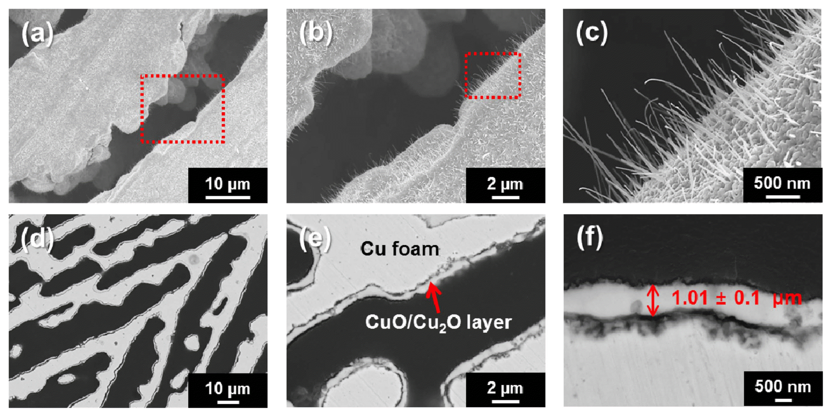
Figure 2(a-c) shows FE-SEM images of the fabricated Cu foam’s morphologies, which are seen both parallel (a, b) and perpendicular (c) to the temperature gradient (perpendicular to the Cu mold bottom surface). The Cu foam morphology (p = 63%) created from the water-solvent-based slurry shows typical elongated and aligned microwalls 28 μm in width and micropores 37 μm in diameter (i.e., lamellar architecture). The morphology of this architecture can be explained by the characteristics of ice crystal growth. During freezing, the growth parallel to the thermal gradient occurred much faster than the growth perpendicular to the thermal gradient, resulting in the formation of lamellar ice-crystal walls aligned along the freezing direction.12-14) Fig. 2(d) compares the XRD patterns of the fabricated Cu foam before and after the continuous reduction and sintering process in a 5% H2/Ar atmosphere. According to the XRD patterns, the starting CuO powder was completely reduced to the metallic Cu foam. To grow a Cu oxide layer on the surface of the Cu foam, the fabricated Cu foam was thermally oxidized at 400°C. As a result, nanowire-like Cu oxide was able to grow radially on the entire surface of Cu foam, as observed in the SEM images of Fig. 3. It is apparent from Fig. 3 that the edges of the wall struts were completely covered with Cu oxide layers, which is confirmed by both the top-(a-c) and side-view (d-f) SEM images; furthermore, the average thickness of the oxide layer was measured based on the side-view images (e, f) and was estimated to be 1.01 ± 0.1 μm. With increasing magnifications (b, c), the presence of the nanowire-like morphology of the Cu oxide layer was more clearly confirmed.
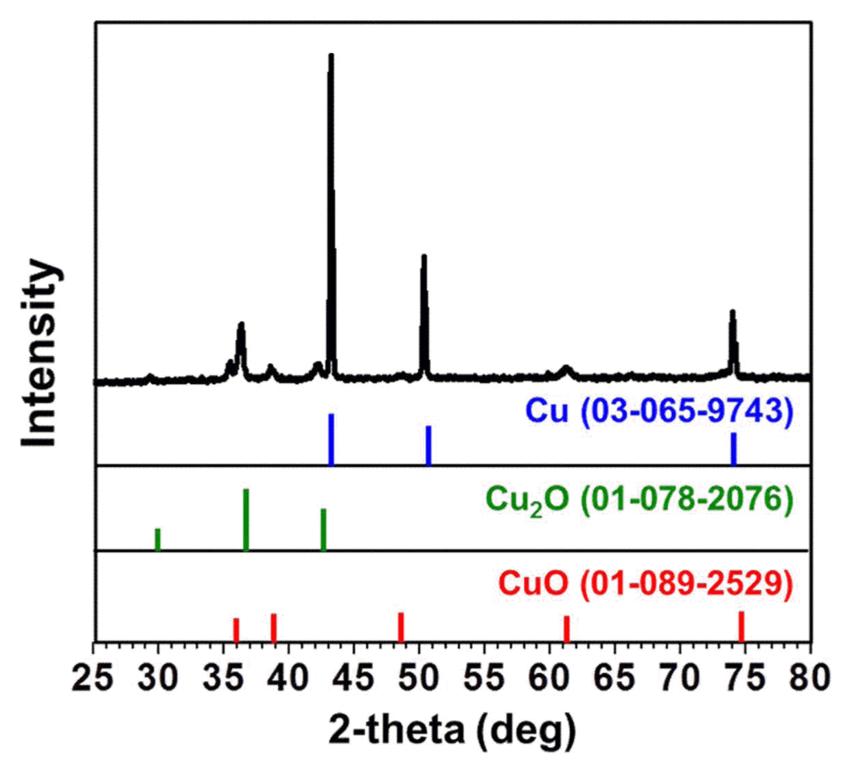
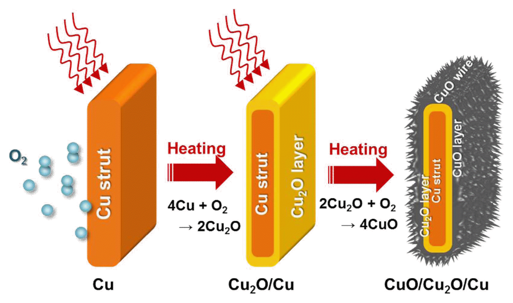
The formation of a mixture of Cu oxide layers on the Cu foam was also verified by the X-ray diffraction peaks of the CuO and Cu2O phases (Fig. 4), which are capable of reacting with and storing Li ions;2-6) additionally, no peaks of any impurities were observed (Fig. 4). Fig. 5 schematically shows the Cu oxide formation mechanism on the surface of the Cu foam. In general, the Cu2O phase is first formed on the surface of Cu; with increasing O content, the CuO phase, which forms through the sacrifice of the Cu2O layer, becomes more dominant. This transition from Cu to Cu2O and to CuO can also be understood from the perspective of their crystal structure. The Cu2O phase has the same cubic structure as the pure Cu phase, where the CuO phase has a monoclinic structure. Therefore, the initial transformation from the pure Cu phase to the intermediate Cu2O phase is more thermodynamically favorable than the direct transformation from Cu to CuO, because lattice reconstruction is required for the formation of monoclinic CuO.5) Under the relatively short heat treatment at 400°C for 30 min conducted in this study, CuO and Cu2O oxide layers were confirmed to coexist (Fig. 5). Despite the importance of an active material’s weight knowledge for the determination of capacity, we could not precisely determine the exact ratio of the CuO and Cu2O phases in this study and assumed that only the CuO phase existed on both the Cu foam and foil electrodes (a conservative lower bound of capacity estimation) on the basis of the fact that there is small difference between their densities with their fair performance comparison being still valid. A Rietveld refinement calculation technique may be used for an estimation of the weight ratio of CuO and Cu2O phases.
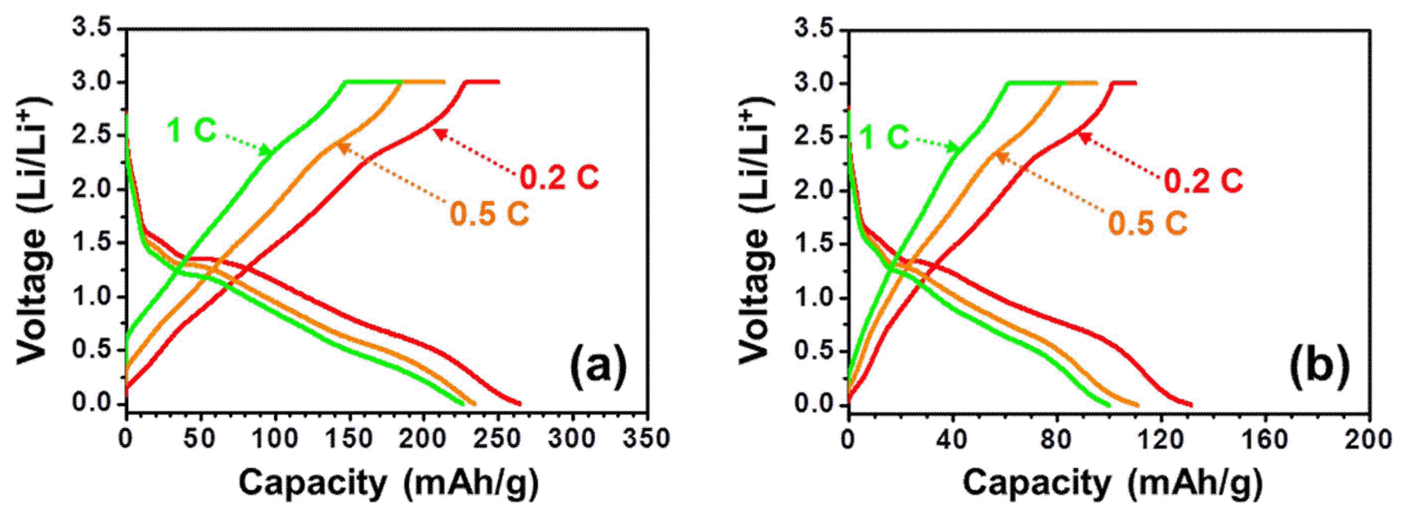
In this electrode design, Cu foam acts as an anode current collector and the Cu oxide layer grown on the surface of the Cu foam acts as an active anode material (Fig. 1). As shown in Fig. 6, the Li storage performance of the Cu foam anode with a nanowire-like CuO/Cu2O active layer was evaluated at scan rates of 0.2 C to 1 C (Fig. 6(a)) and compared with that of the baseline Cu foil with the active CuO/Cu2O layer grown under the same condition (Fig. 6(b)). The initial discharge curves in both cases exhibit two plateaus at the potentials of 1.7 - 1.3 V and 1.3 - 1.0 V (depending on the scan rate), which likely correspond to the transformations from CuO to Cu and Li2O (Eq. 1) and Cu2O to Cu and Li2O (Eq. 2).5,15)
Remarkably, the anode design with a Cu foam current collector (p = 63%) with a nanowire-like CuO/Cu2O active layer exhibits over twice as much initial capacity as that of the baseline Cu foil at the same scan rate (e.g., 264.2 vs. 131.1 mAh/g at 0.2 C), although the capacity of 264.2 mAh/g measured for the Cu foam current collector with a nanowire-like CuO/Cu2O active layer is expected to further increase with increasing volume fraction of CuO. The relatively lower capacity of the CuO/Cu2O anode with the Cu foam current collector than those reported for CuO/Cu2O may be explained by the tendency of the gap formation between the Cu and Cu oxide layers,16) though a further systematic analysis is required for a conclusive evidence.
To the best of our knowledge, this study is the first demonstration of a Cu oxide layer grown on freeze-cast Cu foam for its potential use as an anode in advanced LIBs. Although a major focus has so far been made on the amendment of Cu oxide morphologies for the improvement of poor electronic conductivity and capacity fading during cycling,17,18) the use of porous Cu current collector combined with a thermally grown Cu oxide layer may be a promising solution to these issues. This is because the porous Cu current collector can provide a large surface area and a unique three-dimensional (3D) structure, which can facilitate the transport of Li ions and electrons, and accommodate volume expansion.19-21)
4. Conclusions
In summary, the porous CuO/Cu2O/Cu anode architecture was fabricated on the basis of a facile and scalable design strategy consisting of a combination of water-based slurry freezing and sintering with subsequent thermal oxidation without the common use of a binder and conducting material in the preparation of the battery electrode. As a result, the electrochemical performance of the Cu foam as an anode current collector showed superior capacity compared with the baseline Cu foil as the conventional current collector owing to its unique 3D architecture. It is expected that the micro-porous CuO/Cu2O/Cu foam anode design demonstrated in this study will also be useful for other advanced applications in energy areas.


