1. Introduction
The recent rapid development of display technology has led to active research and development of next generation displays including TFT-LCD, QD-LCD, and OLED, as well as component performance and fabrication process improvements. Among the display technologies, LCD is a non-self-luminous display, so an additional light source device called a back light unit (BLU) is located at the rear of the display to provide a uniform planar light. The BLU is composed of a light guide panel, reflector, diffusion sheet, and two prism layers.
The diffusion sheet refers to the collection of the light diffusion layer, which integrates the binder resin and the organic or inorganic particles used as light scatterers, and the base film. Here, the light diffusion material has been required to have a high light diffusibility for uniform surface emission and to simultaneously have high transmissibility, in addition to maintaining high luminance by focusing the diverging light from the light source.
However, light diffusion materials used in conventional technology have not been able to simultaneously satisfy the requirements of high light diffusibility and high transmissibility. Generally used light diffusion materials include organic particles like PMMA, polystyrene, and inorganic particles like silica.1-7) When organic particles are used as the light diffusion material, the organic particles electrify the light diffusion layer surface, making it easier for foreign substances to adhere; the process of using an organic solvent to remove such foreign substances causes luminance degradation. Also, some organic light diffusion particles do not sufficiently disperse in the binder even when a dispersant is used, and although the particles have high total light transmittance, the particles have low haze, resulting in inadequate light diffusibility and durability degradation over time.8-13) Meanwhile, it is difficult for inorganic light diffusion particles to establish a uniform dispersed phase; also, while high light diffusivity can be attained for certain concentrations and higher, there is a limitation to this content due to the severely inferior transmissibility.14)
As a result, in this study, micro hollow plate type silica with low refraction property was synthesized and applied to a hollow structure as an optical structure to develop a light diffusion material that can simultaneously satisfy requirements of light diffusibility, high transmissibility, and high luminance. The optical properties of the developed material applied to a light diffusion film were evaluated. Furthermore, optical simulation was carried out to compare the obtained optical property results and empirical data.
Micro hollow plate type silica was fabricated the core-shell precipitation method which employed Mg(OH)2 as the core and sodium silicate as the silica precursor. The optical properties of the hollow silica, according to the shell thickness, were investigated by controlling the shell thickness of the hollow silica through varying of the silica precursor and precipitant concentrations.
2. Experimental Procedure
2.1. Micro Hollow Plate Type Silica Synthesis Process
In this study, the hollow silica light diffusion material was synthesized using the core-shell precipitation method with micro plate type Mg(OH)2 particles as the core. Before the silica shell formation reaction, Mg(OH)2 powder (Mg(OH)2, KISUMA5A, 98%, average particle size 0.8 μm, KISUMA, Netherlands) was mixed with DI water at a concentration of 0.8 M followed by 20 minutes of dispersion using a sonicator. The DI water used here was mixed with NaOH to have a pH value of 12. The pH was set at 12 because, compared to when the pH is neutral, particle dispersibility is improved due to the higher zeta potential value of Mg(OH)2 at pH 12.
The fabricated Mg(OH)2 dispersion was poured into a 3-neck reaction vessel and stirred at 350 RPM while the temperature was raised to 50°C. When 50°C was reached, 0.9 M sodium silicate (Na2OSiO2, sodium silicate solution, Na2O 9~10%, SiO2 28~30%, DAEJUNG, Korea) and 0.9 M ammonium sulfate ((NH4)2SO4, ammoniumsulfate, 99.5%, JUNSEI, Japan) aqueous solutions were simultaneously dropped in at a rate of 5 g/min using a metering pump. After continuing this for 3 h, the primary silica shell formation reaction was terminated.
Prior to the secondary shell formation reaction, the silica/Mg(OH)2 core-shell particles formed by the time the primary reaction had ended were sufficiently washed using a vacuum filter; particles were then dispersed in distilled water. Afterwards, sulfuric acid diluent at a concentration of 20% was added at a rate of 7 g/min to remove the Mg(OH)2 core particles. The added sulfuric acid diluent penetrated to the core particles through the pores of the silica shell and removed the core particle by dissolving it. When the shell thickness increases, the sulfuric acid diluent cannot penetrate to the core particle to completely remove it, and so the core particle was removed before carrying out secondary shell formation reaction.
The secondary shell formation reaction was carried out by dispersing the hollow silica particles with the core particles removed in the distilled water again. In this study, to control the hollow silica shell thickness, the amounts of silica precursor and precipitant added in the secondary reaction were varied. Table 1 shows the variation conditions of the silica precursor and the precipitant concentrations in the secondary reaction. Similar to the primary reaction, the secondary reaction involved stirring at 350 RPM while increasing the temperature to 50°C, followed by simultaneous dropping of sodium silicate and ammonium sulfate aqueous solutions to maintain the reaction for 3 h.
After the secondary reaction was terminated, a vacuum filter using hollow silica was employed to perform sufficient cleaning; this was followed by drying at 100°C for 12 h to produce micro hollow plate type silica. The synthesis process diagram is shown in Fig. 1. The hollow silica shape and shell thickness, according to the precursor concentration, were investigated through Field Emission Scanning Electron Microscope (FE-SEM, Nova SEM 450, FEI Co., accelerating voltage 10 kV) and Transmission Electron Microscope (TEM, Tecnai G2 F20, FEI Co., accelerating voltage 200 kV, BF mode) analyses.
2.2. Optical Property Evaluation of Light Diffusion Film with Applied Hollow Silica
In this study, a hollow silica applied light diffusion film was fabricated and, when the film was layered on top of the light source, the light source luminance, transmissibility, and haze variations were measured to investigate the applicability of this hollow silica material as a light diffusion material.
In order to evaluate the optical properties of the light diffusion film, the volume of hollow silica added during light diffusion film fabrication was fixed and the shell thickness of the hollow silica was varied as the coating parameter.
The hollow silica applied light diffusion film was fabricated by coating the polycarbonate (PC) with a coating solution made by mixing a PMMA resin (Acyl resin, PMMA 88~92%, SAMHWA PAINT, Korea) and MEK (Methyl Ethyl Ketone, 99%, OCI.Co., Korea) diluent.
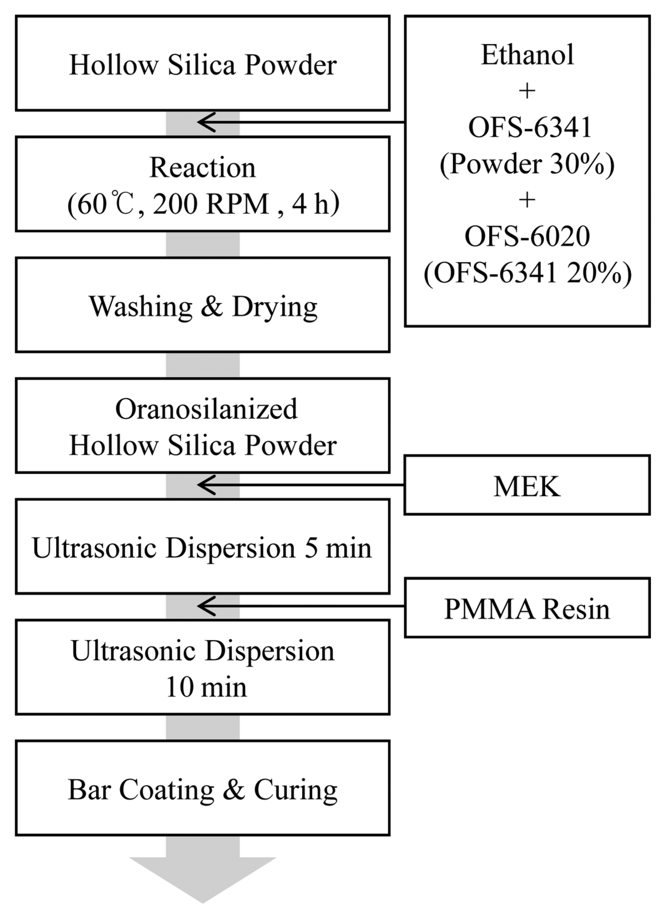
Prior to fabricating the coating solution, to enhance the dispersion of the hollow silica powder within the organic solvent and resin, hydrophobicity was produced by substituting the hydroxy group of the hollow silica surface with an octyloxy group. The following procedure was followed for the hydrophobic surface treatment. Octyltriethoxysilane (OFS-6341 silane, 98%, 276 g/mol, Xiameter, USA) of mass corresponding to 30% of the mass of the hollow silica to be substituted and aminoethylaminopropyltrimethoxysilane(OFS-6020, 100%. 222 g/mol, Xiameter, USA) of mass corresponding to 20% of the added octyltriethoxysilane were mixed in ethanol to produce a solution that was added to the hollow silica powder dispersed solution when the dispersed solution was heated to 60°C. Then, to substitute the surface group, the mixture was reacted for 4 h with stirring at 200 RPM.
The following describes the coating solution fabrication method. To prevent resin impregnation through the shell pores by increasing the dispersibility of the hollow silica in the resin and filling the hollow interior with MEK before resin mixing, MEK was added to the hydrophobicity substituted hollow silica powder, followed by 5 minutes of ultrasonic dispersion. The MEK that filled the hollow interior is volatile; as such, it is removed during the drying process so that the hollow structure in the coating film can be maintained. However, if the resin is impregnated in the hollow interior, the resin hardens in the hollow interior during the drying process and this removes the effect of the hollow structure. The coating solution fabrication was finished by adding the PMMA resin to the hollow silica dispersed MEK solution and performing ultrasonic dispersion for 10 minutes; fabrication of the film was completed by conducting bar coating with a thickness of 3.9 um using a 10 bar on the PC film followed by 10 minutes of curing at 90°C. Fig. 2 shows the fabrication process of the hollow silica applied light diffusion film.
When fabricating a powder mixed coating solution, adding a mass of x relative to the solid resin is conventional, but in this study the powder volume rather than its mass was fixed, because hollow silica powder of different shell thickness, which is a coating parameter, was to be added. If the shell thickness of the hollow silica changes, the powder content changes significantly, so fixing the mass results in a change in the hollow silica particle number for the same mass. This affects the coating solution viscosity and as a result changes the coating film thickness, which could bring about large errors in the optical property assessment of the optical film. Table 2 shows the coating solution fabrication conditions along with the weight ratio of the hollow silica mass to the solid resin (90%) according to the volume of the added powder.
The luminance of the light diffusion film fabricated with the same 3.9 um film thickness using hollow silica was evaluated using a luminance meter (PR-655, Photo Research Inc.). After installing a planar light source below the fabricated film, PR-655 was used to measure the front luminance of the light source. For the side luminance, an angle mold made using a 3D printer and a probe lens FP-55 (Photo Research Inc.) were used to measure the luminance variation according to measurement angles from 10~170°, as shown in Fig. 3. The haze and total light transmittance according to the hollow silica shell thickness were measured using an NDH-5000 (Nippon Denshoku Industries Co.).
2.3. Hollow Silica Optical Simulation
Optisworks 3D Optical Simulation by OPTIS is software that uses the ray tracing principle from the Monte Carlo method to calculate and track light rays emitted in an irregular direction from a light source, based on the laws of reflection and refraction, at an object interface; the device outputs luminance, light distribution, and illuminance data.
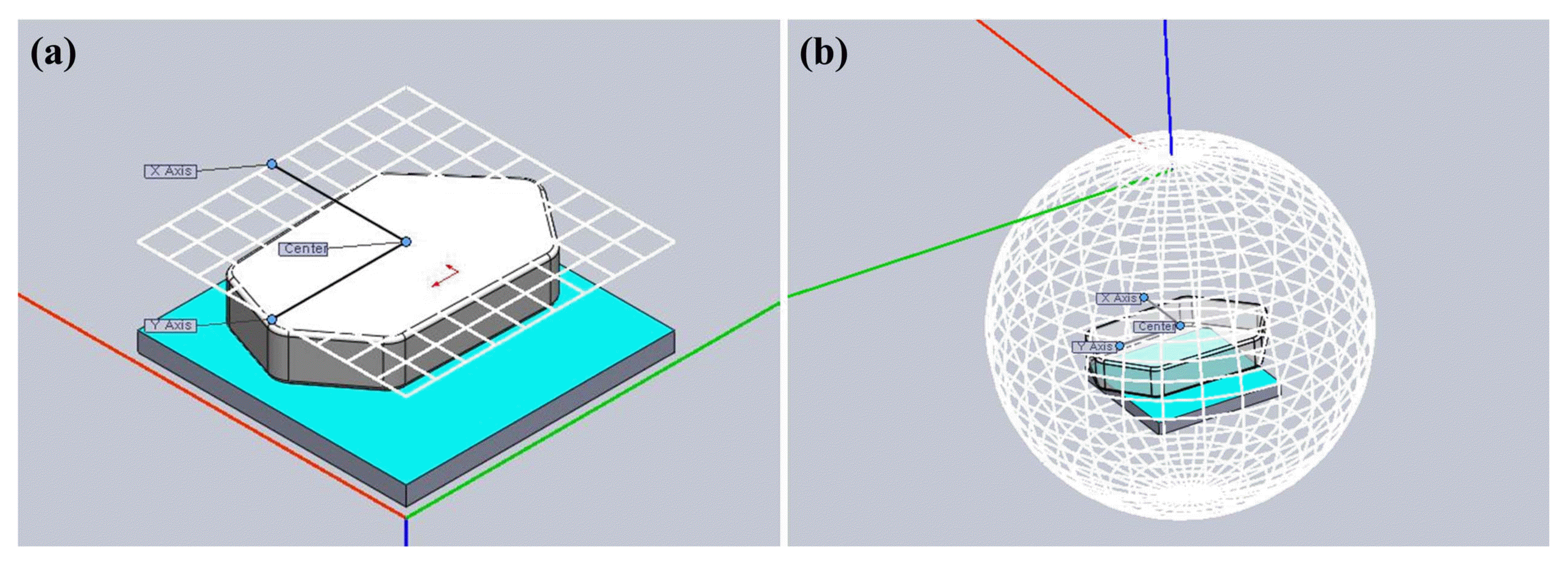
The objective of this study was to comparatively analyze ray paths both when the particle internal structure is hollow and when it is solid, as well as to determine any consequential changes in the light and illuminance distributions. Solid and hollow plate type silica particles were each modeled and both models had surface properties of 80% for transmittance, 20% for reflectivity, and 1.46 for refractive index. The light source was set with a flux of 0.002 and 100005000 light rays were emitted from the light source. After the configuration, each part with applied optical properties was assembled together as one device; the IES detector and illuminance detector were installed as shown in Fig. 4.
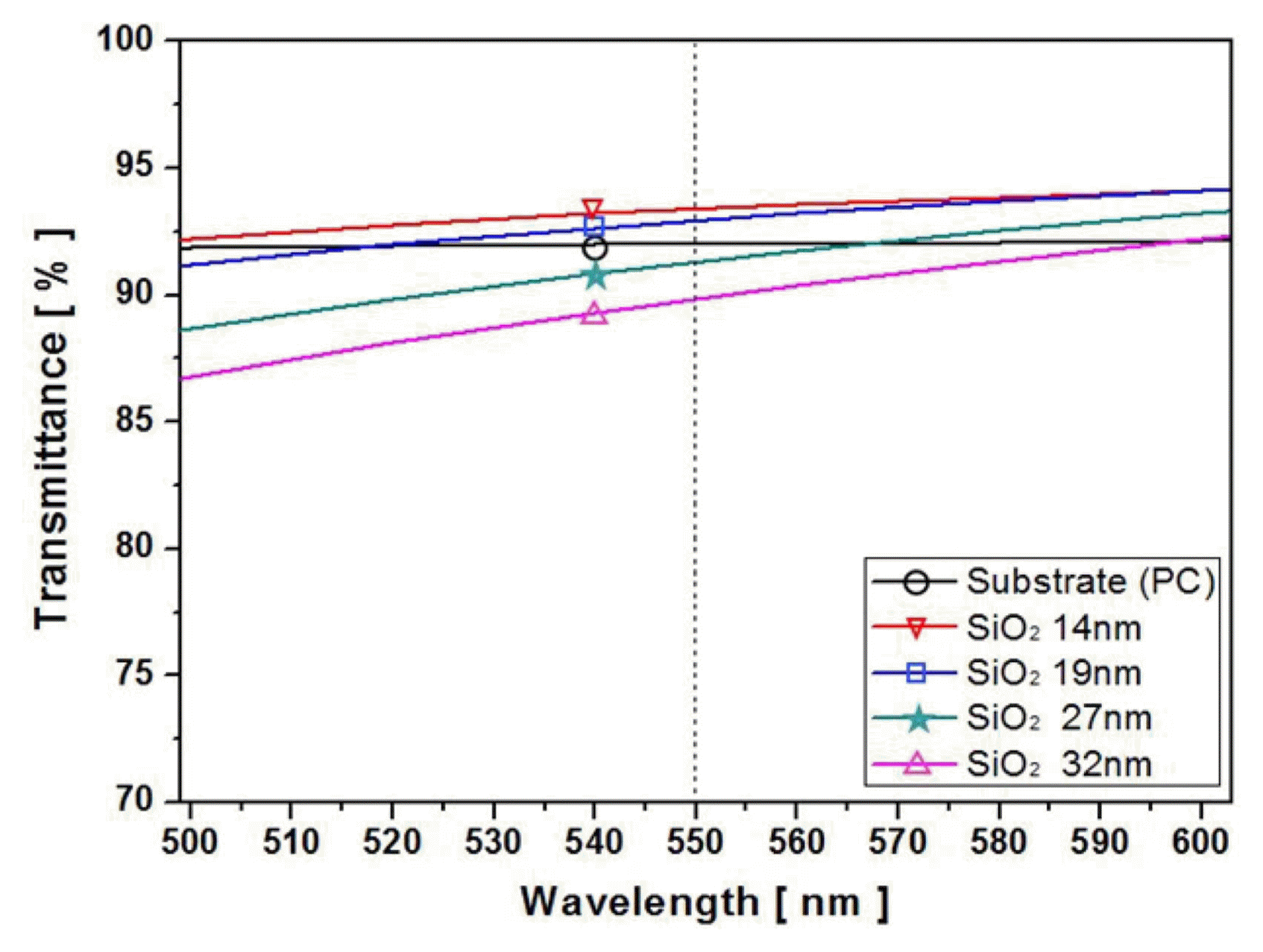
The Essential Macleod program was used to carry out a simulation to determine the transmittance variation according to the hollow silica shell thickness. The material properties of the film were inputted to the program, which then determined the transmittance, reflection, and absorption according to the thickness. So, the hollow silica particles were converted to a silica/air/silica multi-layer structure, as shown in Fig. 5, in which the air layer thickness was set at 100 nm, which was the hollow height identified through TEM, and the silica layer thickness values were set at 14, 19, 27, and 32 nm. Using these settings, transmittance variation simulation according to the hollow silica shell thickness was performed.
3. Results and Discussion
3.1. Hollow Silica Shell Thickness Control According to Precursor Concentration
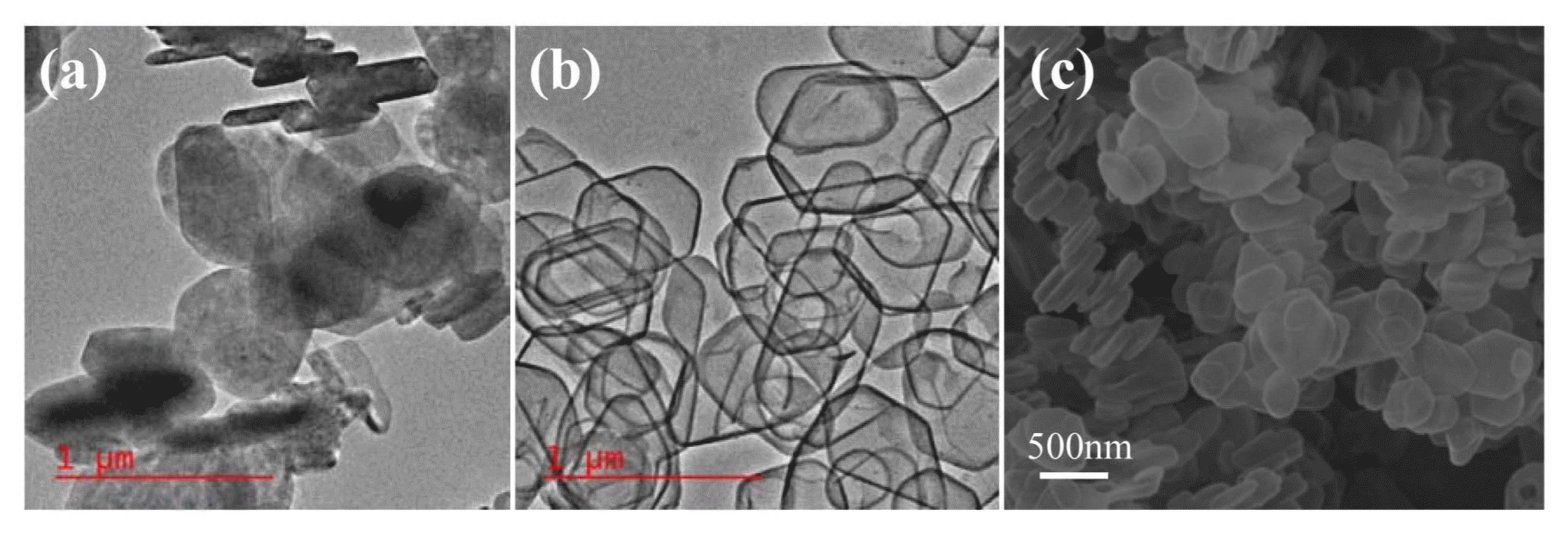
Micro hollow plate type silica was fabricated by forming the silica shell on the Mg(OH)2 core surface and using sulfuric acid treatment to dissolve the core. The mechanism behind the silica shell formation on the Mg(OH)2 core surface can be explained as the synthesis of silica on the Mg(OH)2 core surface due to the dehydration condensation reaction caused by the hydroxy groups of the Mg(OH)2 surface and the silicate ion. Fig. 6 provides TEM images of the Mg(OH)2 core particles and the hollow silica, along with an SEM image of the hollow silica.
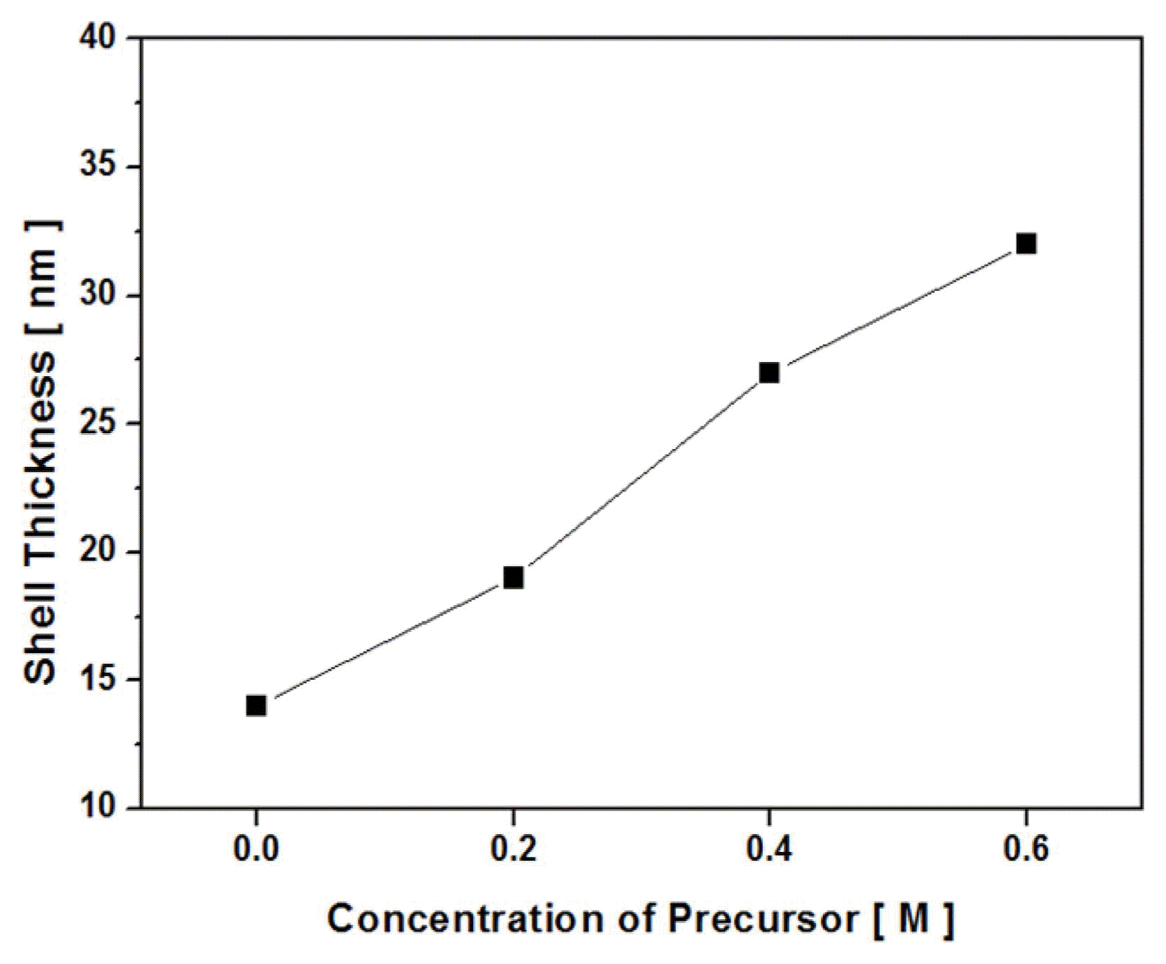
Figure 7 shows the TEM analysis results for the measurement of the hollow silica particle shell thickness according to the silica precursor concentration in the secondary silica shell formation reaction. It was observed that hollow structures were formed for all experiment conditions in which the Mg(OH)2 core particles were completely removed through sulfuric acid treatment. Also, synthesis of hollow silica with smoothly shaped shells was observed. As the silica precursor concentration increased, the shell thickness of the hollow silica increased at a constant rate and, even when excessive amounts of silica precursor were added, independent silica particles did not form; rather, all the added precursor was consumed to form silica shells. The shell thickness when no precursor was added in the secondary reaction was approximately 14 nm, while the shell thicknesses for precursor additions of 0.2 M, 0.4 M, and 0.6 M were around 19 nm, 27 nm, and 32 nm, respectively. The hollow silica shell thickness increased by 5 nm when the silica precursor added amount increased by 0.2 M.
Figure 8 provides a graph plot of the hollow silica shell thickness variation trend according to the silica precursor concentration, based on the TEM analysis results.
3.2. Optical Property Evaluation of Hollow Silica Applied Light Diffusion Film
The optical properties of the light diffusion film fabricated by mixing together hollow silica of different shell thicknesses at varying conditions were investigated. Fig. 9 shows SEM images of the surface, cross sectional, and inside of the hollow silica applied light diffusion film, revealing the particle shape and arrangement. Hydrophobic surface treatment increased the dispersibility of the hollow silica in the resin and it was observed that the hollow silica dispersion within the coating film was uniform. Moreover, observation of the cross section showed that the film thickness was 3.9 um; no blockages due to the impregnation of the resin in the hollow silica particles were observed, and the hollow structure was maintained even within the film.
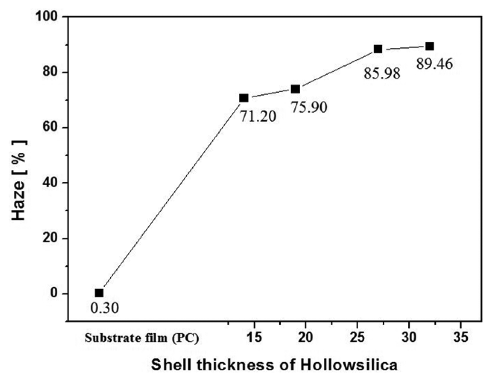
Figures 10 and 11 show total light transmittance and haze measurement results for the light diffusion film obtained using NDH-5000 equipment. When the hollow silica applied light diffusion film was layered on top of the light source, the total light transmittance was 94.55%, which was 4.57% higher than the total light transmittance of the PC film (substrate).
This result can be explained using the concept of Fresnel loss. Some of the perpendicular incident light at the interface between different mediums is reflected and does not pass through. The amount of reflected light gradually increases as the refractive index difference between the different mediums increases. In contrast, if the refractive index difference between the two mediums decreases, the reflection loss of light drops and the overall transmittance increases; thus, the total light transmittance was improved because the hollow silica with low refraction property decreased the refractive index difference at the interface.15,16)
The hollow silica includes an air layer with a very low refractive index (n = 1) within the particle, so a refractive index lower than that of the generally used solid spherical silica (n = 1.46) can be obtained. Here, it was predicted that minimizing the ratio of the hollow silica shell and maximizing the volume of the air layer with a low refractive index will result in a further lowering of the refractive index, and that such reduction will decrease the refractive index difference with the medium (air), resulting in transmittance enhancement. The actual measurement results revealed that the total light transmittance improved when the shell thickness was very small and the total light transmittance decreased from 94.55% to 81.75% as the shell thickness increased.
The haze of the light diffusion film with hollow silica of 14nm shell thickness, which was the thickness with the highest total light transmittance, was 71.20%; as the shell thickness increased, the haze measurements increased from 71.20% to 89.46%.
The total light transmittance and haze were measured for films fabricated using solid spherical silica powder (spherical 6~9 μm, SUNSIL-130, Sunjin Beauty Science, Korea), which is generally used as a light diffusion material, and PMMA powder (spherical 5~10 μm, SUNPMMA-S, Sunjin Beauty Science, Korea) under the same conditions. The measurements showed that the transmissibility when using the PMMA powder was good, with 91.41% total light transmittance and 10.43% haze; however, this sample showed insufficient light diffusing properties. On the other hand, use of the silica powder resulted in 80.91% total light transmittance and 80.72% haze, with excellent light diffusing properties but somewhat low transmissibility. The synthesized hollow silica had a transmittance that was 13.7% higher than that of solid silica and haze that was 9.5% lower than that of solid silica. This result was thought to be due to the hollow structure interacting as an optical structure and altering the optical path, resulting in a focusing effect. Through this result, it was determined that hollow silica exhibits outstanding light transmissibility and light diffusing properties. Application of hollow silica particles as light diffusing material is expected to resolve the transmittance degradation issue of traditional inorganic light diffusing particles.
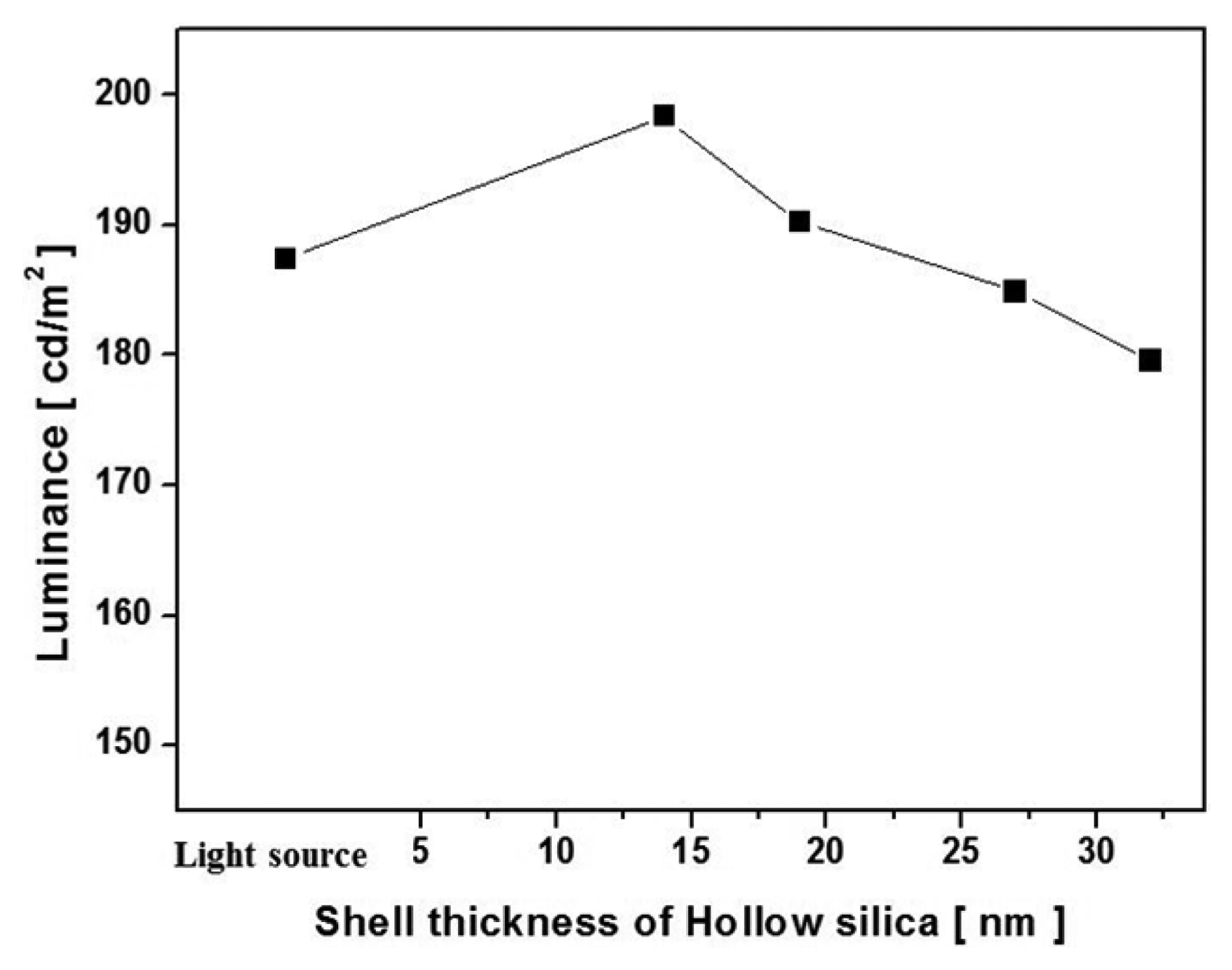
Figure 12 shows a front luminance variation measurement plot according to the hollow silica shell thickness obtained using the luminance meter (PR-655). Measurement of the front luminance variation of the light source when the hollow silica applied light diffusion film was layered on top of the light source showed that there was a luminance enhancement effect due to the application of hollow silica. When the hollow silica shell thicknesses were 14nm and 19 nm, the luminance values were 5.34% and 1.51% higher than that of the light source, respectively. However, when the shell thickness was 27 nm or greater, the luminance decreased. This result was thought to be due to the reduction in total light transmittance with increased shell thickness, as can be observed in Fig. 10.
Figure 13 shows the luminance variation according to the measurement angle, which was measured to analyze the cause behind the increased front luminance of the light source due to the hollow silica applied light diffusion film. For the hollow silica applied light diffusion film, it was found that the luminance tended to decrease compared to the light source luminance for angle ranges of 10~40° and 140~170°, which correspond to side angles, while the luminance increased for the angle range of 50~130°, which corresponds to front angles. On the other hand, the side luminance variation for the solid spherical silica applied light diffusion film was almost the same as the side luminance variation pattern for the light source, and the luminance actually decreased. Through this, it was predicted that the hollow structure of the hollow silica acted as an optical structure, causing a focusing effect and increasing the front luminance.
3.3. Optical Simulation
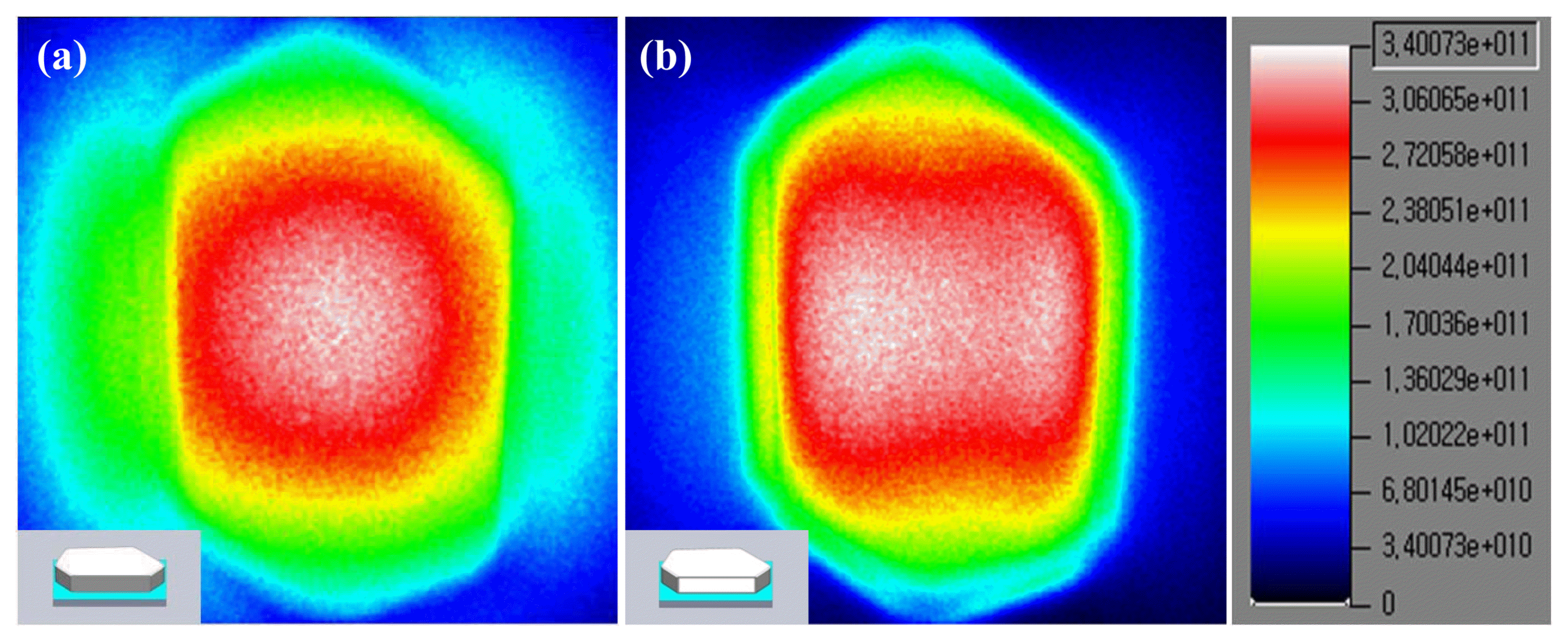
Figure 14, derived from the 3D-optical simulation, shows the illuminance distribution variation according to the presence of the hollow structure within the particle. The blue end of the scale represents low illuminance and the red end represents the high illuminance. For the silica particles including a hollow structure, as shown in (b), it can be observed that the light concentrated at the hollow part increased the illuminance. In contrast, for the solid particle without a hollow structure, as shown in (a), light scattering occurred and the surrounding light increased. Numerically, the average illuminance values for the hollow and solid particles were 3.23e11lx and 2.51e11 lx, respectively. The illuminance of the hollow particle was found to be higher.
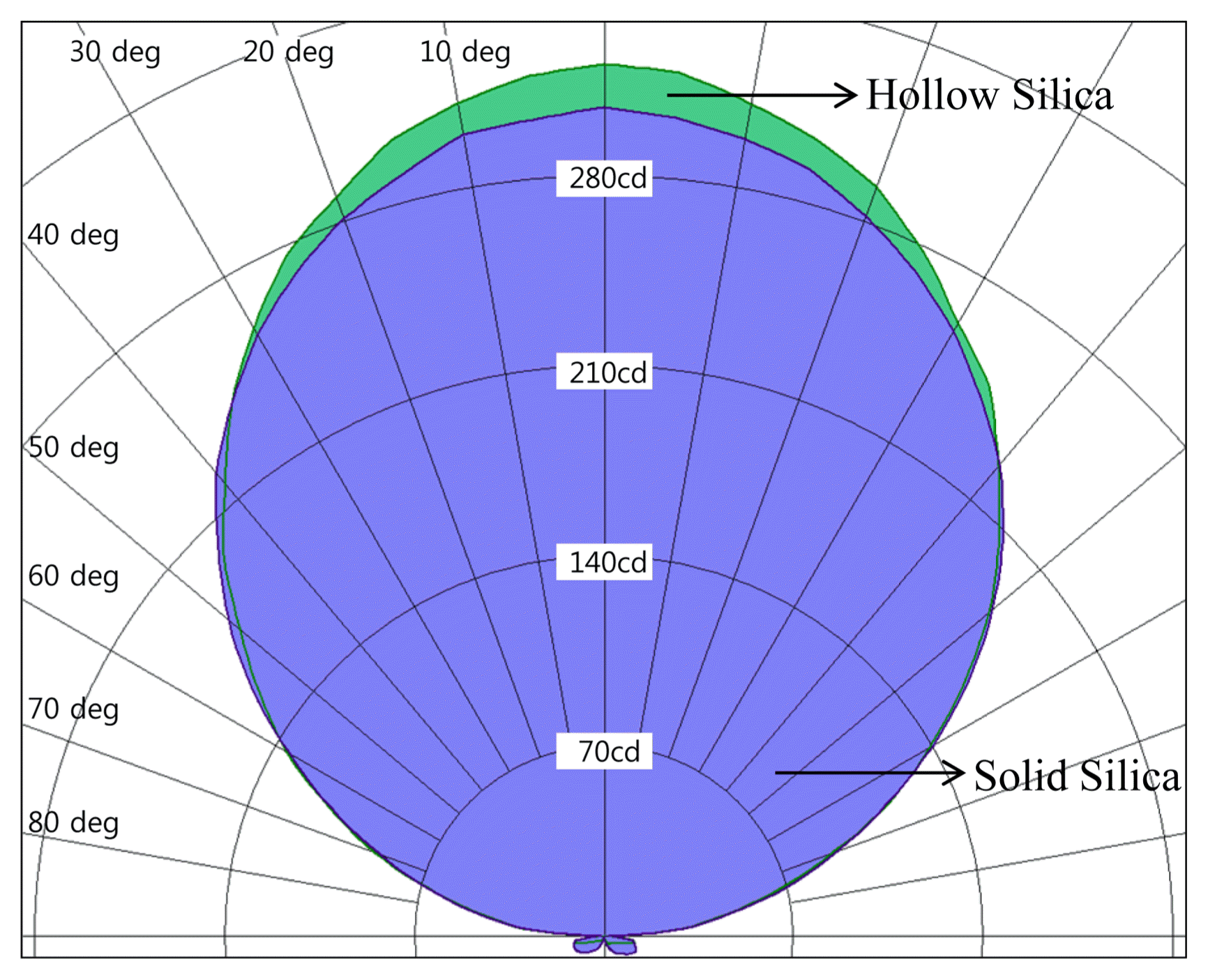
Figure 15 shows the light distribution simulation results according to the presence of a hollow structure in the particle. The front luminance for the hollow particles was higher than that of the solid particles, while the side luminance was lower than that of the solid particle.
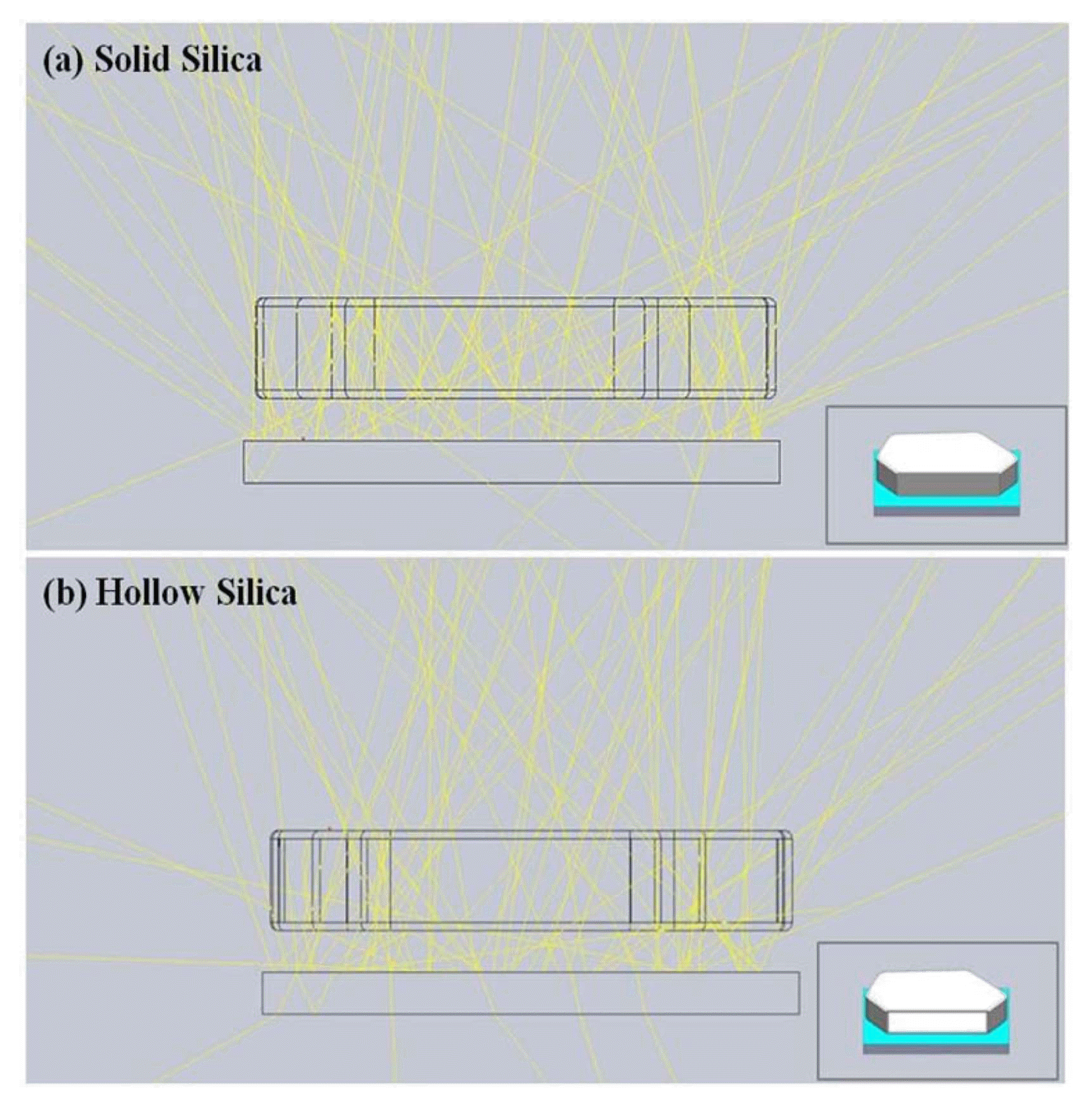
The cause of the illuminance distribution variation and light distribution results can be determined through the light path tracking results shown in Fig. 16. The light that passed through the solid particles was scattered at various angles due to the numerous internal refractions. On the other hand, the light that passed through the hollow particle did not refract but passed through directly at the front. Through this, it was predicted that the hollow structure enhances the straightness of the light to produce the focusing effect.
The results obtained through 3D-optical simulation show trends similar to the real measurement results (Fig. 13), which reveal that the hollow structure reduces the scattering and refraction of light and increases the straightness, resulting in an enhancement of the optical properties.
Figure 17 shows the transmittance simulation results obtained using the Essential Macleod program after converting the hollow silica particle to a silica/air/silica multilayer structure in order to identify the transmittance variation according to the hollow silica shell thickness.
When the silica/air/silica film was layered on the substrate, the transmittance of 550 nm wavelength light increased and this light transmittance increased as the silica film thickness decreased. When the silica thickness was 14 nm, the 550 nm wavelength transmittance increased by 1.5%, while the transmittance decreased by 1.7% when the silica thickness was 27 nm or greater. Through this, it can be observed that the hollow silica shell thickness affects the light diffusion film transmittance. Although the simulation results and the actual total light transmittance measurement results showed similar overall trends, the quantitative values differed because the real light diffusion film is a number of layers of hollow silica particles with irregular particle arrangements, and the number of particles and the particle arrangement could not be included into the simulation design.
4. Conclusions
In this study, micro hollow plate type silica with low refraction properties was synthesized and its hollow structure was applied as an optical structure to develop a light diffusion material that simultaneously satisfies the requirements of good light diffusibility, high transmissibility, and high luminance. The developed light diffusion material was applied to a light diffusion film and the film’s optical properties were assessed.
Micro hollow plate type silica was synthesized by forming a silica shell on an Mg(OH)2 core surface, followed by dissolving the core using sulfuric acid treatment. The concentrations of the silica precursor and precipitant in the secondary shell formation reaction were adjusted to control the shell thickness at 14, 19, 27, and 32 nm.
The total light transmittance of the micro hollow plate type silica applied light diffusion film increased from 81.75% to 94.55% as the hollow silica shell thickness decreased, while haze decreased from 89.46% to 71.20%. The total light transmittance due to the hollow silica light diffusion film increased because of the hollow silica material, which has low refraction properties that decrease the refractive index difference at the medium interface.
When the hollow silica applied light diffusion film was layered on top of the light source, the luminance was 5.34% greater than that of the light source. When the luminance measurement angle was varied, the luminance was found to be lower than that of the light source for the measurement angle ranges of 10~40° and 140~170°, which correspond to side view angles, while the luminance was greater than that of the original light source for the measurement angle range of 50~130°, which corresponds to front view angles. Through this, it was predicted that hollow silica enhances the straightness of the light and brings about a focusing effect. The ray tracking results from the 3D optical simulation showed improvement of the light straightness within the hollow structure.


