


1. Introduction
For solid oxide fuel cells (SOFC), the problem of insufficient durability resulting from high-temperature operation remains to be a key factor impeding commercialization despite such advantages as high efficiency, possibility of internal modification, use of economic oxide electrode, etc.1) Since durability of more than about 40000 h is required for commercialization of SOFC for power generation, considerable efforts to lower operation temperatures of SOFC have been continuously made to enhance the durability of SOFC and allow the use of low-cost stack components such as stainless steels.2-4)
For this purpose, development of electrolyte materials showing a high ionic conductivity even at low temperatures along with ceramic manufacturing technology for preparation of thin electrolytes are required. Materials such as La0.8Sr0.2Ga0.2Mg0.8O3 (LSGM) or Gd-doped CeO2 (GDC) are promising as electrolytes for the low-temperature SOFC. Despite the high ionic conductivities of these materials, however, yttria-stabilized zirconia (YSZ) are still employed most universally for commercialized SOFC due to the problems with the former such as low thermo-mechanical stability and voltage loss caused by partial electronic current.5) While YSZ shows a lower ionic conductivity compared with LSGM or GDC, studies for improving unit-cell performance have been continued through manufacturing of thick-film electrolytes having a thickness of 5 - 10 um by thick-film processes because of their excellent thermal-mechanical stability and durability in diversified fuel conditions such as CH4.6-8)
YSZ exhibits an ionic conductivity at high temperatures due to oxygen vacancies generated by substitution of Zr+4 sites with Y+3 cations through addition of metal oxides of a low valence such as Y2O3 in ZrO2. Also, since Y2O3 increases the mobility of oxygen ions by stabilizing the cubic zirconia structure, zirconia with addition of more than 8 mol% of yttria has been generally used as an electrolyte. Meanwhile, since Sc2O3-stabilized zirconia (ScSZ) among cubic zirconia materials displays a higher ionic conductivity compared with YSZ, much study has been conducted for development of low-temperature SOFC using ScSZ. The high ionic conductivities of ScSZ originate from its similar ionic radius to that of Zr+4 and the resulting crystal structure stability. However, ScSZ with addition of more than 10 mol% of Sc2O3 has a problem of drastic reduction in electrical conductivity because of a phase transformation to a rhombohedral phase (β-phase Sc2Zr7O17) at a temperature below 600°C.3,9-11) Such martensitic phase transition (c → β) brings about 0.15% of volume change, which can cause fracture of a single cell.11) Arachi et al.12) showed that addition of more than 0.5 mol% of CeO2 to 10 mol% Sc2O3-doped zirconia could stabilize the cubic structure of ScSZ. While many studies have been conducted to stabilize the cubic ScSZ structure by co-doping of lanthanum oxides such as Gd2O3, Yb2O3, Y2O3 in addition to CeO2, CeO2 is known to be the most excellent co-dopant thus far.13) However, the rapid degradation problem in comparison with YSZ is delaying the use of 1Ce10ScSZ for low-temperature SOFC despite the high ionic conductivity of the latter.
In the present study, an attempt was made to improve the durability of ScSZ particularly under reducing atmosphere by partial substitution of CeO2 as the stabilizer for ScSZ with different lanthanum oxides (M2O3, M = Yb, Gd, Sm). Ambient-temperature crystal structures were investigated as a function of the type of M2O3 additives, and durability was evaluated by preparing bulk ceramic specimens and measuring electrical conductivities under hydrogen atmosphere for a long time. Electrical conductivity characteristics for Gd- and Ce-doped ScSZ were considered as a function of added amounts of Gd2O3 showing the most excellent durability among additives. Also, electrolyte support type of single cells using electrolytes of 1Ce10ScSZ and 0.5Gd0.5Ce10ScSZ were prepared and their performance degradation characteristics at 850°C were compared.
2. Experimental Procedure
2.1. Preparation of ceramic samples
Electrolytes of 0.5M0.5Ce10ScSZ (M = Gd, Sm, Yb) where CeO2 added to 1Ce10ScSZ (10 mol% Sc2O3-1 mol% CeO2-89 mol% ZrO2) was partially substituted with Gd2O3, Sm2O3, and Yb2O3 (CeO2:MO3 = 1 : 1 molar ratio) were synthesized by solid state reaction. Since all secondary stabilizing elements have the oxidation number of +3, and are cations having a relatively similar size (Gd+3: 1.053 Å, Sm+3: 1.079 Å, Yb+3: 0.985 Å) to the radius for cations of Sc+3 (0.87 Å) or Zr+4 (0.84 Å), a stable solid solution is formed with zirconia.14) Also, electrolytes of xGd(1-x)Ce10ScSZ (x = 0.25, 0.5, 0.75, 1.0) where the added amount of Gd2O3 was increased to 0.25-1.0 mol% were synthesized. Compositions of the synthesized electrolytes are summarized in Table 1.
Stoichiometry was controlled by quantitative mixing of oxide raw material powders (ZrO2, CeO2, Gd2O3, Sm2O3, and Yb2O3). The mixed raw materials were wet-milled for 24 h in ethanol, and dried at 70°C for 24 h, followed by calcination at 1100°C for 5 h. The calcined powders were ball-milled and dried for 24 h again to be prepared as electrolyte powders for ceramic manufacturing. To produce ceramic specimens to be used for evaluation of electrical conductivities, the powder was uniaxially compressed (250 kgf/cm2) to produce plates of 40 × 40 × 4 mm3 and then sintered at 1450°C for 10 h.
2.2. Characterization of ceramics
Sintered densities of ceramic electrolytes were measured by Archimedes method, and all specimens showed more than 95% of relative sintered density as shown in Table 1. Crystal structures for a sintered body of electrolyte were analyzed by X-ray diffractometry (Rigaku, Model no. D/max-2500 VL/PC, Japan). The sintered ceramics were cut into bar specimens of 3 × 3 × 20 mm, and electrical conductivities were measured by 4-probe DC method. Specimens were painted with Pt electrode (Haeraus, Model 6026) and cured at 900°C for 1 h, all of which were loaded inside a tube-type chamber by connecting Pt wire. Electrical conductivity of each specimen in the atmosphere was calculated from the slope by measuring current-voltage curves in the temperature range of 500 ~ 850°C. By using Source-Measure- Unit (Keithley, Model 2400, USA), currents in the range of 1 × 10⁻⁵ - 1 × 10⁻⁴A were applied to the electrodes at both ends of each specimen, and voltage drops between 2 middle electrodes were sequentially measures by using a multimeter (Keithley, Model 2700, US) equipped with a switching module (Keithley, Model 7700, US). To compare degradation characteristics of the electrolyte materials, H2 gas was supplied into the chamber, and electrical conductivities were measured at 850°C for about 50 h.
2.3. Fabrication and characterization of single cells
Through performance evaluation of single cells using the commercial electrolyte, 1Ce10ScSZ and 0.5Gd0.5Ce10ScSZ with 0.5 mol% Gd2O3 addition as an electrolyte, degradation characteristics of each electrolyte were observed. Disk-shaped sintered body of electrolyte formed by uniaxial compaction was polished and electrolyte-supported cells (ESC) of 20 mm in diameter, 0.3 mm in thickness were produced. To coat Ni-ScSZ cermet anode, a slurry was prepared by mixing commercial NiO (Kceracell, 99.8%, Korea) and 1Ce10ScSZ (Daiichi Kigenso Kagaku Kogyo, 99.9%, Japan) powders with a binder in the ratio of 57 : 43 wt. The prepared anode paste was screen-printed, and then sintered at 1300°C for 3 h by 2°C/min. For the cathode functional layer, a LSM-ScSZ composite was used. The LSM-ScSZ slurry was prepared by mixing commercial LSM (Kceracell, La0.8Sr0.2 MnO3, Korea) and 1Ce10ScSZ powders in the ratio of 57 : 43 wt% with plastic additives. The printed cathode layer was cured at 1200°C for 3 h. LSM paste was screen-printed as a current collector layer onto the LSM-ScSZ composite layer, and cured at 1150°C for 3 h to produce ESC. Performance of single cells was evaluated at 850°C, with the both air and fuel fed by 200 ml/min. At operating temperatures, current-voltage characteristics were continuously measured for 250 h by using a Source-Measure-Unit (Keithley, 2400, USA) for the single cell.
3. Results and Discussion
3.1. Phase and electrical properties of 0.5M0.5Ce10 ScSZ (M= Yb, Sm, Gd)
While 1Ce10ScSZ electrolyte is known to have a stable cubic phase crystal structure which shows a high ionic conductivity, the cubic phase (c) and the rhombohedral phase (β) are known to be intermingled as a function of temperature for its crystal structures.13) In the present study, the characteristics of 0.5M0.5Ce10ScSZ electrolyte were evaluated where CeO2 was partially substituted with M2O3 (M = Yb, Sm, Gd) to improve the mixed phase crystal structures (c+β) in the 1Ce10ScSZ electrolyte and the resultant degradation problem in electrical conductivities.
Ambient-temperature XRD analysis result for the sintered specimen of 0.5M0.5Ce10ScSZ electrolyte with substitutional solid-solution of 0.5 mol% of secondary stabilizer (Gd, Sm, Yb) is shown in Fig. 1. As reported in the literature, 1Ce10ScSZ specimen was shown to have a mixture of cubic phase and some β phase. No β phase was detected in the electrolyte where 0.5 mol% Sm2O3 was substitutionally solid-solutioned among the sintered specimens of electrolyte with some CeO2 substituted by secondary stabilizer. However, β phase was detected in the specimens with addition of Gd2O3 or Yb2O3.
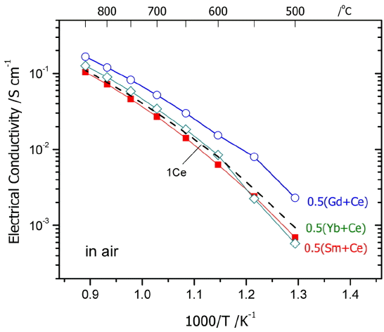
Figure 2 shows the electrical conductivities in air for 0.5M0.5Ce10ScSZ ceramics with addition of 0.5 mol% of M2O3. In a high-temperature section above 700°C, 0.5Gd0.5 Ce10ScSZ with addition of Gd2O3 and 0.5Yb0.5Ce10ScSZ with addition of Yb2O3 showed slightly higher electrical conductivities compared with 1Ce10ScSZ. Electrical conductivities for the electrolytes with addition of 0.5 mol% of M2O3 were highest in the order of M = Gd > Yb > Sm. As shown in Table 1, such differences in electrical conductivities would not have been caused by the fraction of pores present inside the specimens, since all specimens fired at 1450°C for 10 h showed high sintered densities of more than 95%. In that case, the differences in electrical conductivities should be considered by division into grain conductivity and grain boundary conductivity. Grain boundary conductivity is determined by size of the grain, impurities in the grain boundary, space charge layer, etc. However, since the grain boundary resistance for zirconia is not large at a high temperature above 700°C,9,15,16) its effect may be excluded.
First, grain conductivity is affected by the symmetricity caused by phase transition from the cubic fluorite structure to the tetragonal or rhombohedral phase. This is because the mobility of ions shows a higher value in a symmetrical structure. In Fig. 2, electrical conductivities of other specimens showed a gradual change as a function of temperature unlike 0.5Yb0.5Ce10ScSZ which showed a marked change in the slopes below 600°C. Also, activation energy values at high temperatures did not show a large difference, suggesting that there was no large difference in the crystal phases at a high temperature being attributable to additives. In Fig. 1, a rhombohedral phase (β phase) was observed when CeO2 was partially substituted with Yb2O3, Sm2O3, or Gd2O3. However, since the specimen with addition of Yb2O3 where a relatively large amount of rhombohedral phase was observed showed a higher conductivity than the specimen with addition of Sm2O3, the effects of existence of β phase present at ambient temperature on electrical conductivity are presumably not large. However, in view that the specimen with addition of Yb2O3 exhibited a drastic reduction in conductivities below 600°C, the content of β phase with a relatively large resistance appears to have been increased. Based on the high-temperature XRD results, Yarmolenko et al.13) reported that the commercial 1Ce10ScSZ ceramic electrolyte showing a metastable cubic phase at ambient temperature was transitioned back to a cubic phase at a higher temperature after transition to a rhombohedral phase around 300 - 500°C. These authors demonstrated it by obtaining 95% of rhombohedral phase after annealing the 1Ce10ScSZ electrolyte at 400°C for 12 h. Therefore, the ambient-temperature crystal phases of 0.5M0.5Ce10ScSZ shown in Fig. 1 appear to be metastable phases, most of which were transitioned to a cubic phase at temperatures above 500°C where electrical conductivities were measured. However, even if a small change in the amount of additives may not greatly affect the crystal structures at a high temperature in the present study, the fine difference in symmetricity of a cubic structure can bring about a change in the electrical conductivities. Since lanthanide ions substituted for Zr sites have respectively different ionic radii, the effects of the added stabilizers on lattice distortion and the corresponding reduction in oxygen ion mobility should be considered. However, additional studies such as high-temperature XRD analysis and impedance analysis are required for the clearer analysis.
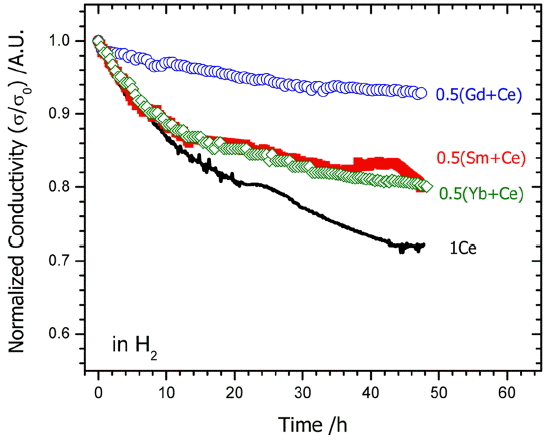
To consider the degradation characteristics of 0.5M0.5 Ce10ScSZ where a part of Ce was substituted from 1Ce10 ScSZ electrolyte, changes in electrical conductivity at 850°C under hydrogen atmosphere were observed. Fig. 3 represents normalized (σ/σ0) electrical conductivities for electrolyte specimens of each formulation under H2 atmosphere. (σ0 being the initial conductivity value.) Whereas 1Ce10ScSZ electrolyte exposed to H2 atmosphere at 850°C for about 50 h showed the highest degradation rate (~ 28%), 0.5Gd0.5 Ce10ScSZ with substitution of Gd showed the lowest degradation rate.
A study on the degradation phenomenon of 1Ce10ScSZ has been conducted by Omar et al.17) These authors reported that continued reduction in conductivities was observed in air and the degradation progressed faster particularly under the reducing atmosphere although addition of 1mol% CeO2 improved the phase stability of scandia stabilized zirconia. The cause for such degradation in a long term test at 600°C for 3,000 h was considered to be caused by an increase in grain boundary resistance, which was attributed to formation of blocking layers impeding diffusion of oxygen vacancies as Ce+3 was gradually diffused to the grain boundary from inside the grain. Also, Ni solid solution from an anode material such as Ni-based cermet was reported to affect the phase transition of ScSZ and the corresponding degradation characteristics. 15,18) Therefore, since the concentration of Ce+3 was reduced when a part of CeO2 was substituted with lanthanum oxide (M2O3, M = Yb, Gd, Sm), more excellent durability is expected to be observed in comparison with 1Ce10ScSZ. However, additional studies are required to find the causes for delaying of the degradation rates by addition of Gd2O3 in comparison with that of Yb2O3 or Sm2O3.
Meanwhile, concerning the degradation phenomenon under an oxidizing atmosphere, Du et al. reported that almost no effects of aging were observed in 1Ce10ScSZ while tetragonal → monoclinic phase transition and serious degradation phenomenon occurred only in ScSZ with additions of 4 mol% and 6 mol% Sc2O3.3) Such results are in agreement with the results of Haering and Yamamoto on the effects of aging at 1000°C in air.11,19) Haering et al. attributed such degradation in the electrical conductivities to the lowered mobility of oxygen vacancies as dipoles
[ S c Z r ′ - V O · · ] · [ S c Z r ′ - V O · · - S c Z r ′ ] X V O · ·
3.2. Effects of Gd2O3 co-dopant substituted into 1Ce10ScSZ
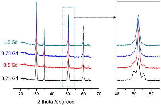
In the 3.1 above, 0.5Gd0.5Ce10ScSZ with addition of Gd2O3 showed the lowest degradation rate. To investigate the effects of Gd content on electrical conductivity, xGd(1-x) Ce10ScSZ specimens were prepared with the added amounts of Gd2O3 being varied within 0.25 - 1 mol%. In Fig. 4, XRD analysis results for the ceramic specimens are shown as a function of the amounts of Gd-substituted solid-solution. In the specimens with formulations of 0.25 - 0.5 mol% for the substituted solid-solution amount of Gd2O3, the metastable β phase was observed, while a single cubic phase was confirmed with a formulation of more than 0.75 mol% for the substituted solid-solution amount. Namely, the amounts of metastable phase (rhombohedral, β) at ambient temperature were reduced, as the more Gd2O3 was substituted in lieu of CeO2 as a structure stabilizer.
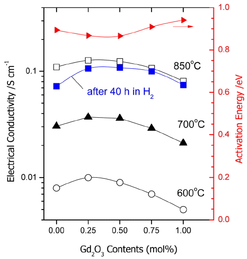
Figure 5 shows changes in the electrical conductivity and the activation energy at 600, 700, and 800°C as a function of an increase in added amounts of Gd2O3. When the Gd2O3 addition were 0.25 - 0.5 mol%, the highest electrical conductivity occurred, and a tendency for reduction was observed with an increase in the concentrations. Such feature is a typical phenomenon occurring when the acceptor concentrations are increased in YSZ or ScSZ, and caused by reduction in the concentration of mobile oxygen vacancies due to association of oxygen vacancies
[ M Z r ′ - V O · · ] ·
Meanwhile, addition of 0.25 - 0.5 mol% Gd2O3 not only enhanced the conductivity of 1Ce10ScSZ, but also improved the durability under hydrogen atmosphere. Also, the durability was increased under hydrogen atmosphere, the more increased the added amount of Gd2O3. This is probably associated with stabilization of the cubic structure resulting from an increase in Gd2O3 contents as shown in Fig. 4.
3.3. Electrolyte-supported cell with 0.5Gd0.5Ce10ScSZ
In Fig. 6, a change in output performance as a function of time for ESC where 1Ce10ScSZ electrolyte and 0.5Gd0.5 Ce10Sc SZ electrolyte were used is shown along with a current- voltage curve. Considering the thickness of electrolyte (300 μm), a relatively high output density of more than 0.8W/cm2 was observed at 850°C. Open-circuit voltages (OCV) of two cells were different, being 1.08 V and about 1.31 V, respectively. The low OCV observed with 1Ce10ScSZ was caused by an increase in the electronic concentrations due to a reduction of
Ce + 4 ( Ce Zr × → Ce Zr • + e ′ )
4. Conclusions
1Ce10ScSZ stabilized to a cubic structure by CeO2 co-dopant showed a rapid degradation in the electrical conductivities particularly under the reducing atmosphere. In the present study, all of Gd2O3, Sm2O3, and Yb2O3 added to partially substitute for CeO2 showed stable electrical conductivities compared with 1Ce10ScSZ, and 0.5Gd0.5Ce10ScSZ showed the highest ionic conductivity together with the lowest degradation rate. In the investigation of electrical conduction characteristics as a function of added amounts of Gd2O3, addition of 0.25 - 0.5 mol% Gd2O3 was observed to exhibit the highest electrical conductivity, and degradation rates under the hydrogen atmosphere was affirmed to be lowered as a result of addition of Gd2O3. In agreement with an increase in durability under the hydrogen atmosphere, the single cell using 0.5Gd0.5Ce10ScSZ electrolyte showed an improved durability as compared with 1Ce10ScSZ.