


1. Introduction
SOFCs are high-temperature fuel cells (with an operating temperature of approximately 1,000°C.) that have used yttria-stabilized zirconia (8mole% Y2O3, 8YSZ) electrolyte for over 30 years with the perovskite La1-xSrxMnO3(LSM) as a cathode and Ni-YSZ cermet as an anode. In contrast with other fuel cells, the high operating temperature enables direct electrochemical oxidation of hydrocarbons. This allows the use of various fuel sources such as H2, CO, CH4, CH3OH, and naphtha. In addition to these advantages, they offer a relatively long service life (approximately 60,000 h or 7 years) and have been verified in terms of thermal durability.
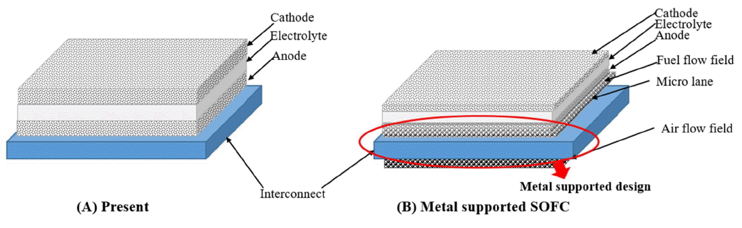
In the case of ceramic-supported SOFCs, which are being extensively studied, mechanical strength and thermal properties are achieved by using a thicker anode to control polarization characteristics. While the use of ceramic-supported SOFCs leads to enhanced electrical conductivity given their high operating temperature, they limit the use of metallic materials. This leads to constraints in not only lowering fabrication costs but also related to resistance to thermal shock, mechanical strength, and properties beneficial for commercialization such as miniaturization and lightweight. To overcome these issues, recent studies have focused on a metal-supported integrated cell structure that provides satisfactory performance at low temperatures, as shown in Fig. 1. The two main advantages of metal-supported SOFCs are as follows.
➀ The significant decrease in thickness allows smaller and lighter cells.
➁ The use of a metal support (high strength, low cost) over ceramic (brittle and expensive) is advantageous in terms of mechanical strength, thermal properties, and costs.
Considering the importance of worldwide trends in metal-supported SOFC research for performance assessment, this paper reviews development trends with a focus on fabrication methods. Furthermore, a novel fabrication method developed in KAIST is discussed.
2. Development Trends of Metal-Supported SOFCs
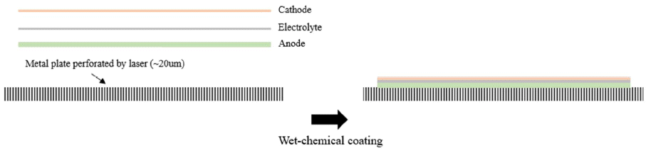
Ceres Power Ltd. and Imperial College have jointly developed metal-supported SOFCs, reporting a power density greater than 0.3 W/cm2 at 600°C. Fig. 2 shows the fabrication process for SOFCs used by Ceres Power. The ferritic stainless steel is perforated to create a gas permeable region, and the fabrication process for ceramic-supported SOFC single cells is applied. The three-layer electrolyte consists of a cerium gadolinium oxide (CGO) layer (~20 μm) for mechanical integrity and gas-tightness, a thin-film YSZ layer to block electronic conduction, and a CGO buffer layer. For improved sintering of the CGO layer, cobalt oxide or copper oxide was used as a sintering aid. Ni/CGO(20 ~ 30 μm) was used as an anode, LSCF/CGO(10~30 μm) as a cathode, and Ti-Nb stabilized Cr alloy (~100 μm) as the metal support.1-2)
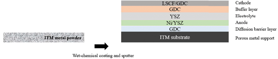
Plansee recently developed a metal-supported SOFC using an autonomously developed ITM substrate. The metal is fabricated on a porous metal attached to a metal plate at the boundary. This newly designed metal substrate showed good performance in protecting the metal, even upon exposure to high temperatures. Furthermore, to fabricate a dense electrolyte, YSZ/gadoliuia-doped ceria (GDC) sputtering was applied. They reported a power density of about 0.5W/cm2 at 820°C. As shown in Fig. 3, the cell consists of an LSCF/GDC cathode, GDC buffer layer, YSZ electrolyte, Ni/YSZ anode, GDC diffusion barrier layer, and ITM metal support.3)
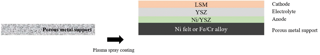
The German Aerospace Center (DLR) has fabricated thin-film SOFCs on a porous metal support, as shown in Fig. 4, reporting a cell performance of 0.6W/cm2 at 800°C. Ni felt and Fe/Cr foam are used as the metal support, YSZ (~25 μm) as an electrolyte, Ni/YSZ (~35 μm) as an anode, and LSM (~30 μm) as a cathode. Vacuum plasma spray (VPS), dip-coating, and electron beam physical vapor deposition (EB-PVD) methods were applied to deposit the electrolyte on the metal support.4)
As shown in Fig. 5, Topsoe fabricated metal-supported cells using a tape cast powder metal porous support and infiltrated nano-structured electrodes. The maximum output density was approximately 0.4 W/cm2 at 650°C. Metal powder containing Fe and Cr was used as the metal support to attain a thickness of less than 400 μm, and LSCF containing CGO was employed as the cathode material.4)
As outlined above, the leading groups in metal-supported cell research have used CGO-based electrolytes or adopted expensive fabrication processes such as vacuum plasma deposition or laser plasma. These high-cost techniques are inadequate for commercialization purposes. As such, more affordable fabrication processes are necessary for the commercialization of metal-supported solid oxide fuel cell stacks.
3. A Novel Fabrication Method: Sinter-joining
In KAIST, a new metal-supported SOFC has been developed to improve the yield of large-area cells and facilitate mass production. The suggested high temperature sinter-joining process (Fig. 6) conducts sinter-joining of the ceramic single cell and metal plate at high temperature. A bonding layer consisting of NiO/YSZ and STS powder was introduced. The new metal-supported SOFC single cell enhances mechanical properties and minimizes the use of sealants when forming stacks. A low-cost process based on in-situ sintering was applied for the cathode and buffer layer, allowing large cells of 100 mm × 100 mm to be fabricated more easily.
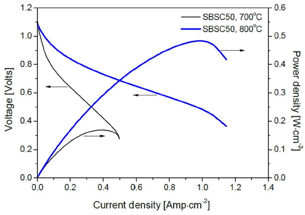
Figure 7 shows a 5 × 5 cm2 metal-supported SOFC with stainless steel or Crofer22APU as the metal support. Both metals exhibit a high smoothness, and Crofer22APU showed outstanding resistance to oxidation and deformation at high temperatures. As shown in Fig. 8, a power density of 0.5 W/cm2 was achieved at 800°C.
Large-area metal-supported cell fabrication technology with high smoothness is a key factor in stack design. At present, the thickness of metal supports and ceramic cells is less than 1 mm, and the overall thickness of metal-supported cells can be maintained below 1 mm if high-strength ceramic cells are developed for metal-supported cells.
The fabrication of metal-supported cells is considered as a key technology for SOFC commercialization. While high costs and fabrication challenges have impeded commercialization, the suggested technique not only lowers the manufacturing cost for metal-supported cells but also enables the fabrication of large-area cells.
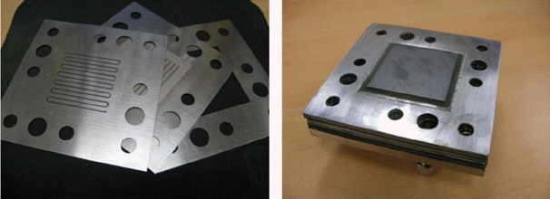
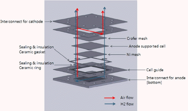
Figure 9 shows the metal-supported bipolar plate, with inner manifolds, designed for the metal-supported SOFC stack. The plate was fabricated using metal plate brazing and diffused bonding technology.
To minimize the use of the sealant, which is a major problem in existing ceramic single cell stacks, metal-metal diffusion bonding and laser welding were applied to the metal-supported sheet and bipolar plate.
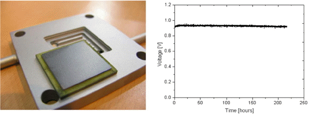
Figure 10 shows the metal-supported SOFC short stack fabricated for a performance evaluation. The 5 × 5 cm2 metal-supported cell was placed in the bipolar plate and brazed for sealing. The results for long-term operation show that the cell performance drops by less than 1% when operated for 200 h at 800°C.
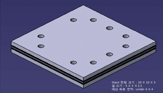
As shown in Fig. 11, the overall stack size is 10×10×5 cm3 with a 50 mm × 50 mm metal-supported single cell. The effective area of the single cell is 40 mm × 40 mm, or 16 cm2. The intake manifolds of air and fuel were verified through a computational analysis, and the stack was designed such that air and fuel are supplied in a counter-flow configuration. Hydrogen sealing was achieved by welding the metal support and metal bipolar plate, and air sealing by MICA. Glass or ceramic sealants, commonly associated with problems in ceramic-supported stacks, were not used (Fig. 12).
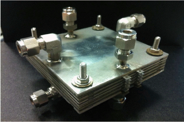
To observe the practicality of the designed stack, a prototype was developed, as shown in Fig. 13. After investigating the possible problems, a 50 mm × 50 mm metal-supported five-layer stack was fabricated. Currently, stack measurements are being taken, and the stack design will be reassessed based on the results. An 80 mm × 120 mm stack will be developed followed by a performance evaluation.