


1. Introduction
rogress of eco-friendly anode materials for lithium ion batteries (LIBs) with high energy efficiency, good power density, and long cycle stability is required in the fields of renewable energy sources, portable electronics, and electrical vehicles.1-2) To this end, iron oxide (Fe3O4) as an anode material for LIBs has been considered due to its high theoretical capacity (~ 926 mAh g−1), natural abundance, and non-toxicity.3-4) Even though iron oxide has many advantages, its practical applications for LIBs have still been hindered by the low electrical conductivity and poor structural integrity induced by the huge volume expansion during the alloying/de-alloying process with Li ion. There are many approaches to solving these drawbacks, such as applying nanoparticles (NPs), nanorods, and nanotubes of Fe3O4.5-6) On the other hand, hybrid structures of iron oxide nanostructures with carbon or composites of iron oxide with carbon conductors can improve electrical conductivity, accommodate Li ions, and act as volume expansion buffer sites.7-9) Thus, the structural and electrical properties of iron oxide can be implicitly improved. Iron oxide nanoparticles/MWCNTs (iNPs/M), with improved electrical conductivity and high surface area, can provide a suitable conductive matrix, high Li ion accommodation, and mechanical integrity, allowing iron oxide to endure the volume expansion during the cycling test. We demonstrate this unique nanostructure using a facile route of microwave-assisted hydrothermal process to prepare hybrid structure Fe3O4 nanoparticles with MWCNTs. The as-prepared iNPs were obviously in the magnetite crystal phase (Fe3O4), which was coated on the MWCNTs surface with ~ 50 nm of iNPs. This hybrid nanostructure of iNPs/M exhibited a specific discharge capacity of ~664 mA h g−1 after the 100th cycle at a current density of 200 mA g−1, while iNPs without MWCNTs showed a specific discharge capacity of ~122 mA h g−1 after the 100th cycle. The surface interior of the iNPs with MWCNTs is an ideal electron carrier to iNPs, which could offer resistance to volume expansion of the iNPs during the cycling, improvement of the high rate capability, and better cyclability. The improved electrochemical performance of the hybrid structure of iNPs/M can be ascribed to the unique structure of the iNPs, which are homogeneously anchored with conductive MWCNTs.
2. Experimental Procedure
2.1 Material preparation
The iNPs were synthesized by a facile microwave-assisted hydrothermal process (MARS 6, CEM Co.). 1.29 g of FeCl3·6H2O was dispersed by magnetic stirring for 2 h in 35 ml of deionized (DI) water. Consequently, 1.49 mL of C3H10N2 was added to the FeCl3·6H2O solution and transferred to a Teflon-sealed vessel and maintained at 150°C for 5 min with a ramp rate of 5°C/min. The iNPs of red solid products was centrifuged with 5 times its volume of DI water and dried in a vacuum oven at 80°C for 12 h. On the other hand, iNPs/M was concurrently synthesized with 50 mg of acid treated MWCNTs under the same conditions as those used for the iNPs. Dark red precipitation of iNPs/M was observed, which indicated that the iNPs were well anchored as nanoscale particles.
2.2 Material characterization
The surface morphologies of the iNPs and iNPs/M were confirmed by field emission scanning electron microscopy (FE-SEM, Hitachi S-4200 system). The crystal phase and structures were investigated by X-ray diffraction (XRD, Rigaku RINT).
2.3 Electrochemical characterization
Electrochemical experiments were carried out using 2032 coin cells. The working electrode was prepared using the active material (80 wt%), polyvinylidene binder (20 wt%), and 1-Methyl-2-pyrrolidinone without conductive carbon black. The present slurry was formed using a doctor blade on copper foil (20-μm-thick) and then dried in a vacuum oven at 80°C for 12 h. Consequently, the as-prepared copper foil was punched by 12 φ dimeter electrodes. The Li foil was used as a counter electrode. The electrolyte was 1 M LiPF6 in EC:DEC (1:1). The coin cells of iNPs and iNPs/M were cycled in a cut-off range from 0.015 to 3.0 V using a WBCS 2000 at room temperature. Electrochemical impedance spectroscopy (BioLogic, VSP-300) results were obtained between 1 MHz and 100 mHz at the open circuit voltage (OCV).
3. Results and Discussion
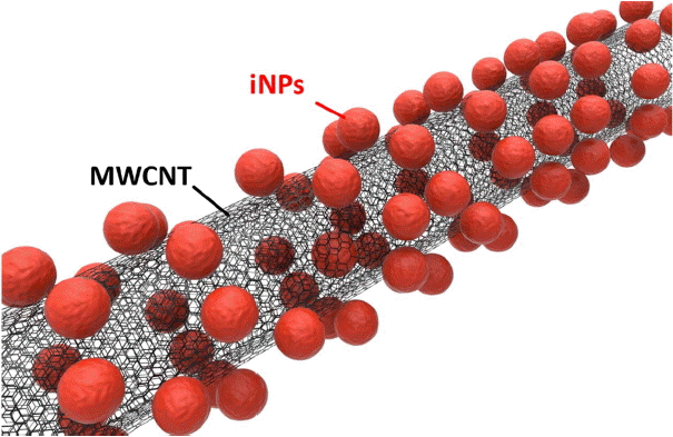
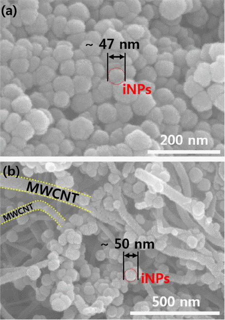
Figure 1 provides a schematic illustration of the iNPs/M structure obtained via simple microwave assisted hydrothermal process; this structure consists of iNPs and MWCNTs. The SEM images (Fig. 2) show the structure and morphology of the iNPs and iNPs/M. The nanostructure of the iNPs with diameter of ~ 47 nm (Fig. 2(a)) shows agglomerated nano-powders. On the other hand, the iNPs of the iNPs/M were clearly anchored on the surface of the MWCNTs; this was observed by SEM imaging, with results shown in Fig. 2(b). The structure of the iNPs/M, which had a diameter of ~50 nm, presents a uniform distribution on the MWCNTs. The hybrid structure of the iNPs/M enhanced the charge transfer, preventing volume expansion during the alloying/dealloying process due to the free space, and offering a short diffusion length of the Li ion. The presence of the acid treated MWCNTs probably provided heterogeneous nucleation sites during the hydrothermal synthesis of the iNPs.
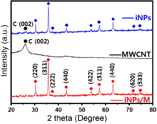
The structure and crystal phase of the iNPs, MWCNTs, and iNPs/M were investigated by X-ray diffraction (XRD) with a 2 theta range of 20 - 80°. As can be confirmed in Fig. 3, the iNPs, and iNPs/M have a cubic Fe3O4 phase (magnetite, JCPDS No. 65-3107), with a lattice parameter of 50.8393 nm. The XRD spectrum of the MWCNTs was clearly indexed by carbon (002).
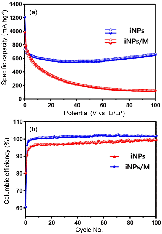
The electrochemical performances of the iNPs and iNPs/M were evaluated by galvanostatic charge and discharge at 0.2 C (200 mA g−1) in a voltage window of 0.01 - 3.0 V (Fig. 4). The specific capacity of the iNPs and iNPs/M electrodes at the first cycle are ~ 987 and ~ 1208 mA h g−1, which are close to the theoretical capacity of the Fe3O4 phase. The iNPs show high specific capacity at the first cycle with a high irreversible capacity. The initial capacity at the 1st cycle and the reversible capacity of the iNPs at the 2nd cycle are ~ 987 and ~ 788 mA h g−1; these values continuously dropped to ~ 122 mA h g−1 at the 100th cycle, which indicates that the iNPs electrode presented poor cycle characterization and unstable electrochemical behavior. These may be due to volume expansion of the iNPs and sn electrical breakdown between the current collector and the iNPs electrode during the insertion/extraction process. On the contrary, the specific capacity of the iNPs/M appeared to be about~ 1208 mA h g−1 at the first cycle, with an enhanced capacity retention of ~664 mA h g−1 at the 100th cycle (Fig. 4(b)), which is much higher than that of pure iNPs. The enhanced initial capacity retention of the iNPs/M anode can be attributed to the presence of an MWCNTs supporter. The Coulombic efficiency of the iNPs and iNPs/M at the 1st cycle were about 80 and 60%. These irreversible capacities were induced by the occurrence of a solid electrolyte interphase (SEI) layer, the electrolyte decomposition, the reduction of Fe3O4 to Fe, and the formation of Li2O.5,7,10) Although the iNPs/M anode exhibited a better electrochemical performance, the Coulombic efficiency at the 1st cycle was lower than that of the iNPs, which can be related with the specific surface area being higher than that of the iNPs. At the 2nd cycle, the Coulombic efficiency of the iNPs/M dramatically recovered with increasing cycle number and finally a Coulombic efficiency of 100 % appears at the 100th cycle.
The charge/discharge curves of iNPs and iNPs/M, shown in Fig. 5(a) and (b), exhibit two voltage plateaus at ~0.93 and ~0.8 V during discharge (alloying process). The first voltage plateau at ~ 0.93 V was attributed to the irreversible reaction step of the iNPs. On the other hand, the long plateau at ~0.8 V corresponds to the reduction step of Fe(III) to Fe(0). The dealloying curve appeared as an inclined plateau near ~1.5 V corresponding to the reverse reaction. The iNPs anode showed irreversible capacity behavior with increasing cycle, which is in accord with the capacity vs. cycle plot (Fig. 4(a)). In Fig. 5(b), the iNPs/M anode reveals better reversibility not only in alloying but also in dealloying, which promoted the capacity retention of iNPs/M with increasing cycle and may be expected due to unreacted surfaces that occur during alloying/dealloying.
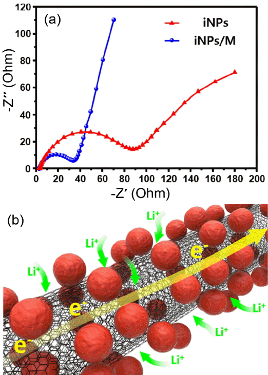
In order to investigate the differences of electrochemical performance between iNPs and iNPs/M, electrochemical impedance spectroscopy was conducted before the cycling test of the specimens, as shown in Fig. 6(a). These results are displayed as a Nyquist plot. There are two kinds of component: 1) a depressed semicircle is generally ascribed to the charge transfer resistance and the interface resistance, which were typically combined as the total resistance of the specimen.11-13) 2) A straight line Warburg constant is observed in the low frequency region, which reflects the diffusion of the Li+ ion from the electrolyte to the surface of the active material. The total resistance of the iNPs/M is 32 Ω, which is lower than the value of 86.9 Ω of the iNPs. The Warburg tail of the iNPs/M is steeper than that of the iNPs, which indicates a faster diffusion kinetics of the Li+ ion. These results can be clarified through the Coulombic efficiency, capacity reversibility, and structural integrity. Finally, the synergistic improvement of the iNPs/M offers structural stability during the volume expansion and capacity retention after the long-term cycle test. This phenomenon of excellent Coulombic efficiency of the iNPs/M was ascribed to the short diffusion length, the electrically conducting network of the MWCNTs, and the good bonding between the functional groups of the acid treated MWCNTs and each of the iNPs and iNPs/M; also, the functional groups of the MWCNTs improved the high accommodation capacity of the Li ion, as illustrated in Fig. 6(b).
4. Conclusions
We developed an environment-friendly synthesis process of iron oxide nanoparticles (iNPs) deposited on acid treated MWCNTs to form a hybrid structure that was fabricated by one step microwave assisted hydrothermal process with a time efficient process. Fe3O4 nanoparticles (iNPs) on the surface of the MWCNTs were uniformly coated. When tested as an anode for Li ion batteries, these iNPs/M exhibited high specific capacity and good capacity retention, e.g., in the 100th cycle, the iNPs/M attained a value of ~ 664 mA h g−1 at a 0.2 C rate. The improved coulombic efficiency and electrical conductivity can be ascribed to the hybrid structure of the iNPs/M. The unique structure of the Fe3O4 metal oxide and the carbonaceous MWCNTs expressly improved the structural integrity due to the presence of nanoscale Fe3O4, the electrical 3D network of the MWCNTs, and the buffering effect of the free volume of the MWCNTs, all of which lead to an accommodation of the serious volume expansion of Fe3O4 during the alloying/dealloying reaction with the Li ion. Such a synergistic effect and unique structure can be applied to other metal oxides that seem to be promising alternative electrode materials for LIBs.