Development of Alkali Metal Thermal-to-Electric Converter Unit Cells Using Mo/TiN Electrode
Article information
Abstract
Molybdenum (Mo), an electrode material of alkali metal thermal-to-electric converters (AMTEC), facilitates grain growth behavior and forms Mo-Na-O compounds at high operating temperatures, resulting in reduced performance and shortened lifetime of the cell. Mo/TiN composite materials have been developed to provide a solution for such issues. Mo is a metal that possesses excellent electrical properties, and TiN is a ceramic compound with high-temperature durability and catalytic activity. In this study, a dip-coating process with an organic solvent-based slurry was used as an optimal coating method to achieve homogeneity and stability of the electrodes. Cell performance was evaluated under various conditions such as the number of coatings, ranging from 1 to 3 times, and heat treatment temperatures of 800 – 1100°C. The results confirmed that the cell yielded a maximum power of 9.99 W for the sample coated 3 times and heat-treated at 900°C.
1. Introduction
Since the Paris Agreement about climate change in 2015, 196 countries around the world have been making greater efforts to solve global environmental issues; to decrease CO2 emissions, the development and utilization of new renewable energy sources has been suggested as a way of reducing the use of carbon-based fuels and increasing energy efficiency.1–3) Among various new kinds of renewable energy, the alkali metal thermal-to-electric converter (AMTEC), an environment-friendly technology enabling power generation using thermal energy transmitted from various heat sources, is a device to produce electric power by using as a driving force for fuel circulation the force caused by the transfer of sodium (Na), an alkali metal, between the evaporation section and the condensation section due to the phase transition, without separate injection of fuel.
In the circulating structure of an AMTEC, Na is changed to gaseous phase in the evaporation section (600 to 800°C), ionized to pass through a beta-alumina solid electrolyte (BASE), and recombined with free electrons and Na ions at a cathode outside the BASE; it is then returned to liquid phase in the condensation section (200 to 400°C) to pass by capillarity through a porous wick, before moving to the high-temperature section.4–8) Early studies on AMTEC were focused on the securing of the ionic conductivity and the high-temperature structural stability of the BASE, the Na ion pathway.9–11) However, due to power loss caused by particle growth in the cell and the durability decrease of the electrodes following continued operation, the need to develop electrode materials has come to the fore. In our previous studies,12,13) to improve the performance and stability of AMTEC unit cells, we developed a core-shell composite powder using, as the core, Mo, which is a conventional electrode material having excellent electric properties; as the shell, titanium nitride (TiN), having excellent high-temperature durability and catalytic properties, was used.
In the present study, we investigated an electrode coating process to improve the performance of AMTEC unit cells using the Mo/TiN composite powder synthesized in our previous studies.12,13) Among various coating processes,14,15) dip-coating was applied in the present study because the resulting substrate shape is less limited, manufacturing may be carried out, and, during coating, the thickness of the coating layer may be easily controlled.16,17) We analyzed the variation of the physical properties and the electrochemical performance of the electrode layers depending on the number of coatings. Na immersion, depending on the temperature of the BAS thermal treatment, was also analyzed to find out the causes of performance change depending on the electrode thermal treatment temperature.
2. Experimental Procedure
2.1. Preparation of Mo/TiN slurry and electrode manufacturing
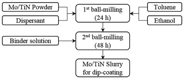
The slurry for the manufacture of the Mo/TiN electrode was prepared by applying the composition shown in Table 1 and the procedures shown in Fig. 1. Following the method in one previous report,13) primary ball milling was performed with a Mo/TiN composite powder synthesized by the Pechini method, using toluene (99.5% absolute, OCI Co., Korea), ethanol (99.9% absolute OCI Co., Korea), and a dispersant (DISPERBYK-110, BYK Inc., USA) for 24 h. Then, a secondary ball milling step was performed for 48 h after adding a binder solution (B74001, Ferro Co., USA) to prepare the slurry for dip-coating. Using the prepared slurry, the dip-coating was performed on the surface of a tube-type BASE (length: 150 mm, diameter: 28 mm, thickness: 1.5 mm) to secure an electrode area of 52.75 cm2; then, the coating was dried at 70°C for one hour. This process including the dip-coating and drying was defined in the present study as a single coating process; this coating process was repeated two or three times. Each of the unit cells after coating was thermally treated at 800 to 1100°C in H2 atmosphere (99.9%, 200 sccm) for three hours. To analyze the physical properties of the manufactured electrodes, the electrode surfaces and cross-sections were observed using a scanning electron microscope (SEM, S-4800, HITACH Co., Japan).
2.2. Evaluation of unit cell performance
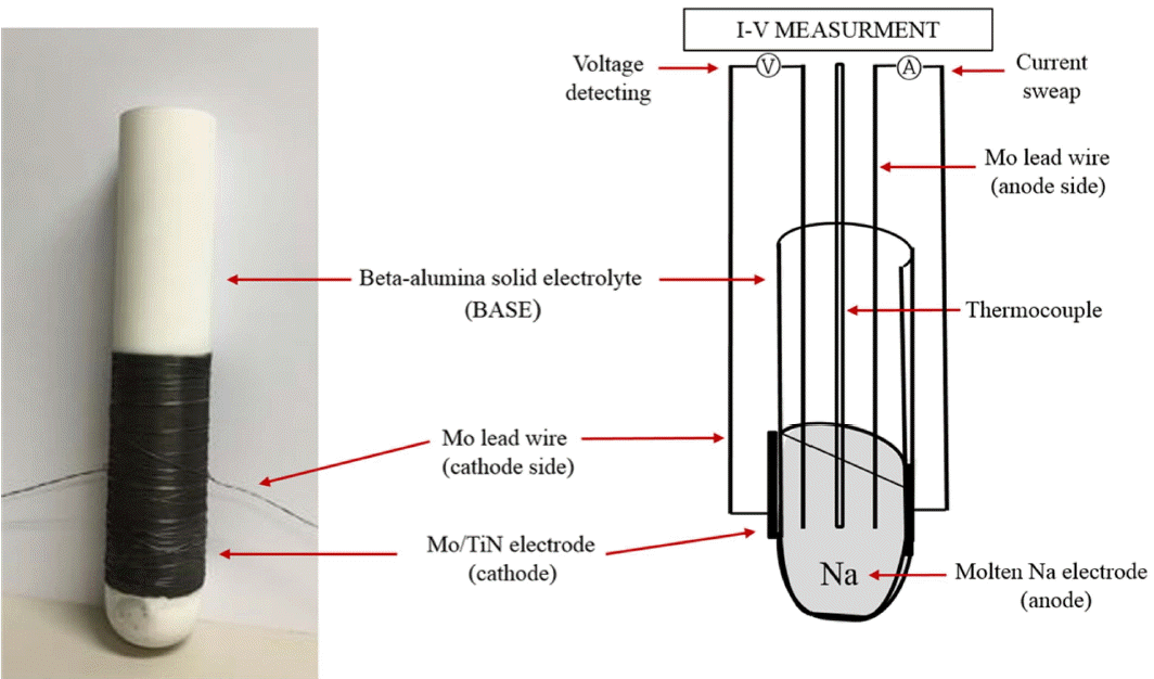
To evaluate the electrochemical performance of the AMTEC unit cells, unit cells having the structure shown in Fig. 2 were prepared. To measure the voltage between the cathode side and the melted Na anode side coated on the BASE, and to apply the electric current, a 4-probe Mo lead wire was connected to the inside and outside of the cell. A thermocouple was installed inside the cell to measure the operation temperature; this temperature was established with reference to the temperature of melted Na.
The electrochemical performance was evaluated through current-voltage measurement using an SP-240 potentiostat (BioLogic Science Instruments, France); the impedance analysis was performed using DC electronic load (ITECH, U.K.).
2.3. Analysis of properties of beta-alumina solid electrolyte
To analyze the variation of the Na content depending on the temperature of the BASE thermal treatment, the thermal treatment was performed at 800, 900, 1000, and 1100°C in H2 atmosphere (99.9%, 200 sccm) for three hours. Using X-ray fluorescence (XRF, Primus II, Rigaku Co., Japan), element analysis was performed on the thermally treated specimens.
3. Results and Discussion
3.1. Analysis of Mo/TiN electrode microstructure
The immersion of a molten Na electrode is a factor have has a direct effect on the AMTEC performance. Molten Na, which is an Na ion pathway, is distributed on the Mo/Tin electrode to cause a direct reaction of Na and Na ions. Hence, an Mo-Tin electrode should have a pore size and a pore volume that enable the immersion of molten Na into the electrode. Fig. 3 and 4 are cross-sectional SEM images of the Mo/TiN electrodes manufactured by dip-coating depending on the thermal treatment temperature and the number of coatings. The surface image in Fig. 3 shows Mo/TiN particle growth by sintering of particles and inter-particle necking due to the increase of the thermal treatment temperature, resulting in a decrease of micro-pores on the electrode surface. The cross-sectional image in Fig. 4 shows that the electrode thickness increased depending on the number of coatings. The thickness of the electrode thermally treated at 900°C in reducing atmosphere following dip-coating was 7 μm after one coating, 14 μm after two coatings, and 32 μm after three coatings. No change in the microstructure of the electrode was observed except for the growth of the coating layer. The growth of the electrode coating layer was proportional to the increase of the pore volume and may enhance the role of the matrix at impregnating more molten Na.
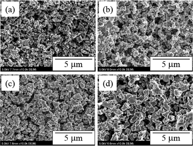
SEM images of top surface of Mo/TiN electrodes heat-treated at (a) 800, (b) 900, (c) 1000, and (d) 1100°C in reduction atmosphere.
3.2. Performance evaluation
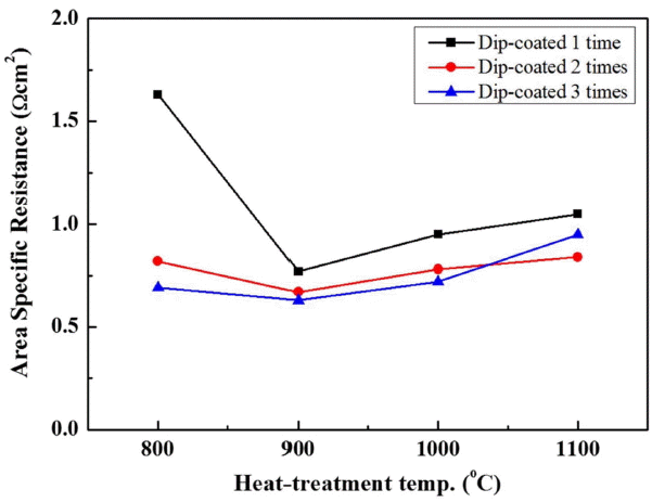
The performance of the unit cells depending on the electrode manufacturing conditions was evaluated. The I-P curve in Fig. 5 shows the power output of the unit cells manufactured by varying the number coatings from 1 to 3 and the thermal treatment temperature from 800 to 1100°C. The power output of the unit cell manufactured by coating the electrode three times and thermally treating it at 900°C was as high as 9.9 W. The power outputs of the unit cell manufactured by coating the electrode two times and thermally treating it at 900°C, and that of the unit cell manufactured by coating the electrode three times and thermally treating it at 800°C were 7.08 W and 5.53 W, respectively. The plot in Fig. 6 compares the maximum power density (MPD) and shows the dependence of the power output on the number of coatings and on the thermal treatment temperature. The comparison of the MPD between the unit cells showed that the performance was better in the unit cells including electrodes thermally treated at 900°C than it was for unit cells including electrodes thermally treated at other temperatures. In the unit cells including the electrodes that underwent thermal treatment at 800 or 900°C, the performance increased as the number of coatings increased. However, in the case of thermal treatment at a temperature equal to or higher than 1000°C, the MPD was either around 50 mW/cm2 or 25 mW/cm2 (three coatings, 1100°C). These results are consistent with the area specific resistance (ASR) values shown in Fig. 7. The ASR in Fig. 7 is the ohmic resistance of an individual ASR and shows a tendency opposite to that of the MPD values: the unit cell showing the highest performance had the lowest ohmic resistance. The performance and resistance distribution may be correlated with the electrode conditions, the change of the Na ion path depending on the molten Na content in the electrode and the Na content in the BASE, and the change of the electrode reaction site.
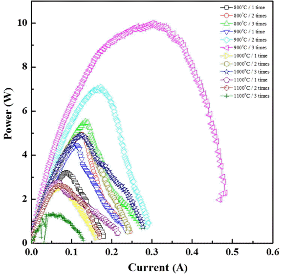
I-P curves of AMTEC unit cell using dip-coated Mo/TiN electrode in various manufacturing conditions.
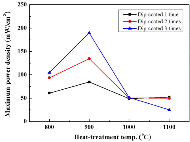
Variation of maximum power density of AMTEC unit cells manufactured by dip-coating process under various conditions.
3.3. Variation of β”-alumina property
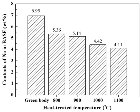
Figure 8 is a plot showing the variation of the Na content depending on the BASE thermal treatment temperature, wherein the Na content was analyzed using XRF and resulting data were converted into weight ratios. The Na content was from about 4% to about 5% in the BASE thermally treated under conditions the same as those for the electrode thermal treatment between 800 to 1100°C, while the Na content of one green body was 6.95 wt%. When thermally treated, Na, of which the melting point is 644°C, had a vapor pressure that increased to evaporation, which brings about the results shown in Fig. 8. The difference of the Na content among the unit cells treated at different temperatures was low (within 2 wt%), except for the case of the green body. However, the difference of the performance due to differences of Na content is very large, as shown by the results of the electrochemical analysis described above. Notably, although the BASE that underwent thermal treatment at 800°C showed the highest Na content, the analysis of the ASR values shown in Fig. 7 in connection with the electrode surface microstructure shown in Fig. 3(a) indicates that the electrode function dropped and the circuit composition of the unit cell became unstable because the thermal treatment of the electrode at such a low temperature prevented necking between the particles, as well as preventing the development of pores to stably impregnate molten Na.
4. Conclusions
This article introduces an electrode manufacturing technology to improve the coating process using Mo/TiN composite powder and provides results, obtained by electrochemical experiments, regarding AMTEC electrode performance. Mo/TiN composite powder was synthesized using Mo, which has excellent electric properties, and TiN, which has excellent high-temperature durability. Composite powder was used to prepare the slurry for dip-coating. The dip-coating method, which enables convenient control of the β”-alumina coating layer, was applied as a coating method; the variation of the performance depending on the number of coatings and on the thermal treatment temperature was investigated. The number of coatings was varied from 1 to 3; the thermal treatment temperature was varied from 800 to 1100°C. The results showed that the highest performance (9.99 W) was found for the specimen that underwent three coatings and thermal treatment at 900°C. In cases of electrodes thermally treated at 900°C, the electrode thickness increased as the number of coatings increased; this had a direct effect on the increase of the cell performance. The Na content in the electrolyte was dependent on the temperature of the electrode thermal treatment. The ionic conductivity and the performance were found to be decreased by thermal treatment at a high temperature due to the volatilization of Na. Hence, electrodes treated at lower temperatures showed better performance, but electrodes treated thermally at 800°C did not show high performance because the necking between the particles and the formation of pores were not sufficient.
In the present study, the manufacturing conditions of AMTEC electrodes were optimized. Further studies will be carried out to improve the wetting of molten Na in electrodes by developing better electrode materials.
Acknowledgements
This work was conducted under the framework of the research and development program of the Korea Institute of Energy Research (B7-2411-01).

