Ceramic Ink-jet Printing on Glass Substrate Using Oleophobic Surface Treatment
Article information
Abstract
Ink-jet printing has become a widespread technology with the society’s increase in aesthetic awareness. Especially, ink-jet printing using glazed ceramic ink can offer huge advantages including high quality decoration, continuous processing, glaze patterning, and direct reproduction of high resolution images. Recently, ceramic ink-jet printing has been rapidly introduced to decorate the porcelain product and the ceramic tiles. In this study, we provide an effective method to apply ceramic ink-jet decorations on the glass substrates using a oleophobic coating with perfluorooctyl trichlorosilane. The ink-jet printed patterns were much clearer on the oleophobically coated glass surface than the bare glass surface. The contact angle of the ceramic ink was maximized to the value of 64.0° on the glass surface, when it was treated with 1 vol% PFTS solution for 1 min. The effects of the printing conditions and firing process on the ink-jet printed patterns on the oleophobically coated glass were also investigated.
1. Introduction
Ceramic ink-jet printing is a technology where high-resolution patterns or images are printed by jetting fine droplets of ceramic ink onto substrates such as tile. Since such ceramic ink-jet printing technology transmits and prints design images in a digital file, faster response to a change in images or patterns desired by consumers with a very high ink efficiency is possible compared with the existing silk printing technology, and eco-friendly processes nearly without production of wastes may be constructed. Due to such advantages, ceramic ink-jet printing has experienced growth at a high rate in the related industrial areas for the past few years.1,2)
Thus far, digital printing technology utilizing the ceramic ink has been applied mainly to life ceramic products or products such as ceramic tile. In addition, application possibilities for design of construction glasses using the outstanding heat resistance and light stability of ceramic inks are also open.3) However, when the same patterns or images are printed on glass substrates and ceramic tiles using an ink-jet printer, there are problems where desired patterns or images cannot be properly expressed as the ink jetted on glass surfaces is spread in 2-dimensions on the glass surface unlike tiles. Control of ink droplets on a glass substrate is related to contact angles between the glass substrate and the ink, and control of the behavior of ink droplets being printed on the substrate by controlling the contact angles between the ink printed onto the substrate and the glass substrate is very important to realize high-resolution images or patterns on glass substrate surfaces by ink-jet printing.
In general, contact angles in the range of about 30 ~ 70° are reported as being required to print patterns on a glass surface,4) To obtain desired contact angles on the glass substrate surface, methods of providing hydrophobic or oleophobic property through surface treatment may be considered according to solvent types of the ink. For the methods of incorporating hydrophobic or oleophobic property in the substrate surfaces, a method where liquid-solid contact friction is lowered by increasing surface roughness through formation of double reentrant or overhanging microstructures in the substrate surface, or a method where the surface energy of the substrate is made to be lower than that for the ink used in printing by controlling the surface energies of the substrate through chemical treatment with particular compounds has been reported.5–11) Due to the characteristics of transparent glass substrates, however, scattering of incident visible light occurs when the surface roughness is increased. This results in hindrance to transparency of the glass substrates. Therefore, when surface energies of glass substrates are controlled, a method of chemical coating may be considered more appropriate than that of forming microstructures on the surface. When the substrate surface is to be provided with hydrophobic or oleophobic property by controlling surface energies through chemical treatment, fluorine-based compounds are mainly used.12) Thus far, aligned close-hexagonal-packed-CF3 group is known to be able to achieve the lowest surface energies,13,14) T. Darmanin et al have reported that fluorocarbons had a lower surface energy than hydrocarbons.15)
In the present study, a black ceramic ink as one of the frequently used colors for ceramic ink-jet printing was synthesized by using a pigment with the composition of ethylene glycol and Co(Fe,Cr)2O4. Also, since the ink jetted on glass substrate surfaces could not be controlled when ceramic ink was jetted on the glass substrate, behavior of the jetted ceramic ink droplets was controlled by providing the glass surfaces with oleophobic property through chemical coating of the glass surface to improve problems of hindering resolution of the printed matter due to 2-dimensional spreading. For the oleophobic coating on glass substrate surfaces, perfluorooctyl trichlorosilane (PFTS) was used and contact angle changes of ceramic ink as a function of experimental conditions as well as behavior changes of the printed pattern as a function of contact angles were observed by changing concentrations of and immersion times in the coating solution.
2. Experimental Procedure
As the ink for ceramic ink-jet printing used in the present study, a black ceramic ink(Co(Fe,Cr)2O4)was employed. For synthesis of the black ceramic pigment, cobalt oxide(CoO, 99%, Aldrich Co.), iron oxide(Fe2O3, Junsei), and chromium oxide(Cr2O3, Junsei) were used as starting raw materials, and wet milling for mixing was conducted for 3 h, followed by firing at 1000°C for 1 h.16,17) The black ceramic pigment thus obtained through solid-state synthesis method was atomized into particles of about 300 nm in size through an attrition mill as one of high-rate rotary milling methods to prevent nozzle blockage of the ink-jet printer upon application to ceramic ink-jet printing and to secure dispersibility of the ink. After undergoing atomization process, the black ceramic pigment was dispersed in a mixed solvent of ethanol and ethylene glycol (99.5%, Samchun), and prepared as a ceramic ink. Also, a cationic surfactant of CTAB(cetyl-trimethylammonium bromide) was added for more stable dispersion of ceramic particles in the ink.
As a substrate for application of ceramic ink-jet printing, soda-lime glass slide (60 × 25 × 3.8 mm) was used, while solutions of PFTS(CF3(CF2)5CH2CH2SiCl3, 97%, Aldrich) diluted in toluene(99.5%, Samchun) to the concentrations of 0.001–5vol% were used for oleophobic coating to lower surface energies of the glass substrate. Prior to coating using PFTS, glass substrates were cleaned for about 30 min using an ultrasonic cleaner, followed by drying in an oven at 80°C for preparation, and immersed for 0.5 to 120 min in a mixed solution of PFTS and toluene. (Fig. 1)
(a) Structural formula of PFTS and (b) Schematic diagram of oleophobic coating on glass substrate using PFTS.
Jetting characteristics of the black ceramic ink were analyzed by using a dropwatcher (CeraDW, STI), and contact angles between substrate and ink were analyzed by using a contact angle analyzer (PHX300, Surface electro optics). Also, pattern printing on glass substrates was conducted by using a sapphire printhead (QS-256/80 AAA, Fuji film dimatrix) with nozzle diameter of about 35 μm, and behavior of the ceramic ink patterns printed on glass substrates was observed under an optical microscope (SZ61, Olympus).
3. Results and Discussion
3.1 Characteristics of black ceramic ink for digital printing
Shown in Fig. 2 are the analysis results for evaluation of properties of the black ceramic ink used and of suitability of the ink-jet printing. Fig. 2(a) shows an XRD result for the black ceramic pigment synthesized by solid-state method. According to the XRD analysis result, the black ceramic pigment could be seen to be a single spinel phase, with no additional second phases being observed. Fig. 2(b) is a TEM image for the black ceramic pigment after atomization process using attrition milling, and it could be affirmed that particle sizes smaller than 300 nm suitable for ink-jet printing process were mostly observed while the ceramic pigment particles had irregular shapes due to the milling process.
(a) XRD spectrum and (b) TEM image of the black ceramic pigment. (c) Optical image and jetting property of the black ceramic ink.
Figure 2(c) shows a picture of the synthesized black ceramic ink along with an image taken by a high-speed camera using a dropwatcher where droplet behavior was changed with elapse of time immediately after jetting of the synthesized ceramic ink from the ink-jet printer nozzle. Through such analysis of jetting characteristics, it was evaluated whether or not smooth jetting of the synthesized black ink from the ink-jet printer nozzle was actually realized and whether the falling ink droplets had an appropriate spherical shape upon jetting of ink droplets. In general, ceramic inks where the phenomenon of satellite droplets with a long tail being formed in the jetted ink droplet and a droplet being split into more than two droplets, as well as the phenomenon of deflection of the ink into different directions rather than falling vertically after jetting of the ink occurred are not considered suitable for the ink-jet printing. In the present study, as the synthesized ceramic ink showed a short tail along with formation of single spherical droplet following elapse of about 200 μs after jetting from the nozzle together with straightness after jetting, it was determined to be suitable for application to ink-jet printing.
3.2 Optimization of surface coating process on glass substrates for application to ceramic ink-jet printing
Figure 3 shows the results of ink-jet printing on a ceramic tile and a glass substrate without surface treatment, respectively, by using the prepared black ceramic ink. While smooth realization of the printed pattern with absorption in surfaces of the ink jetted from the printer could be affirmed in the case of ceramic tile of Fig. 3(a), proper expression of the desired patterns or images could be seen difficult in the case of a glass substrate of Fig. 3(b), since there existed no absorption layers capable of controlling behavior of the jetted ink unlike the preceding ceramic tile. In Fig. 3(c) and Fig. 3(d), differences in ceramic ink behavior between the ceramic tile and the glass substrate can be observed more clearly. To obtain a clearer resolution in the glass substrate with no absorption layers to control behavior of the jetted ceramic ink, control of ceramic ink droplets jetted on the substrate was attempted by controlling surface energies of the substrate through oleophobic surface coating. In measurement of contact angles between glass substrate surface and ceramic ink, the images of the substrate surface and the ink taken by a CCD camera after dropping fine ink droplets onto the glass substrate surface using a micro pump were analyzed for calculation. Used as measured values were the mean values of measurement by jetting for 5 times each.

Ink-jet printed patterns using the ceramic ink on (a) the porcelain tile and (b) the glass substrate. (c) and (d) is the magnified images of (a) and (b).
Shown in Fig. 4 is the result for measuring contact angles with the ceramic ink after surface treatment of the glass substrates using PFTS. Fig. 4(a) and Table 1 show the change in contact angles for the ceramic ink as a function of immersion times of the glass substrate in the solution with 1 vol% of PFTS. The immersion times for the glass substrate were controlled to be 0.5 – 120 min, and the measured contact angle upon immersion for 1 min was 64.0°, representing the largest value among measured contact angles. Subsequently, contact angles of the ceramic ink were gradually reduced, and could be affirmed to have been reduced to 41.4° when the immersion time became 120 min. In Fig. 4(b) and Table 2, the immersion time of 1 min which exhibited the largest contact angle in Fig. 4(a) was made a fixed value, and changes in contact angle of the ceramic ink as a function of PFTS concentration were shown with the PFTS concentrations being controlled to be 0.001–5 vol%. For the changes in contact angle as a function of PFTS concentrations, the minimum value of 29.8° was observed for the PFTS concentration of 0.001 vol%, and the maximum value of 64.0° was observed for the PFTS concentration of 1vol% after a gradual increase with an increase in the concentrations. Afterwards, the contact angle showed a tendency of slight reduction even when the PFTS concentration was increased further.
Contact angles of the ceramic ink on the glass substrate coated using (a) 1 vol% PFTS solution for various immersing time, and (b) various concentration of PFTS solutions for 1 min.
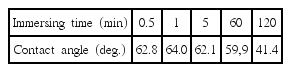
Contact Angles of Ceramic Ink on Glass Substrate Coated Using 1 vol% PFTS Solutions for Various Immersing Time

Contact Angles of Ceramic Ink on Glass Substrate Coated Using PFTS Solutions of Various Concentrations for 1 min
3.3 Droplet behavior of ceramic ink after ink-jet printing and firing processes
Figures 5(a)–5(i) show the results of printing patterns while drop to drop (D2D) distances for the jetted ink were varied to 75 μm, 100 μm, 150 μm on the glass substrate with a change in surface energies by controlling the glass substrates without surface treatment and the concentrations of PFTS coating solution (0.001%, 1%). The contact angles between ceramic ink and glass substrate were measured in the order of the substrate without surface treatment, the substrates with surface treatment using coating solutions with concentrations of PFTS 0.001% and PFTS 1%, where the measured values were shown to be about 10°, 30°, 60°. When D2D value was 150 μm in the glass substrate with a contact angle between ink and glass substrate of 10°, the droplet printed upon the substrate formed a single ink droplet. However, when D2D values were set at 75 μm and 100 μm, respectively, the jetted droplets could not be properly controlled on glass substrate surfaces being spread in 2-dimensions and could be affirmed to be merged with adjacent ink droplets (Figs. 5(a) – 5(c)). When the contact angle between ink and glass substrate was about 30°, the jetted ink could also be affirmed to form single droplets for D2D values of 100 μm and 150 μm (Figs. 5(d)–5(f)). On the other hand, in the case of glass substrate with a contact angle between ceramic ink and glass substrate of about 60°, the ink droplets printed upon glass substrate surfaces could be affirmed to form single spherical droplets rather than being spread in 2-dimensions for the whole range of D2D values (75 μm–150 μm). In the case of substrate with a contact angle of about 10°, the mean droplet size of the jetted ink was measured to be 89.2 μm, while 63.7 μm was observed in the case of contact angle of about 30°. In the case of maximum contact angle measured in the present experiment of about 60°, single droplets of 53.5 μm in size were observed. Based on the above measured values of contact angle, the sizes of the droplets jetted on glass substrate surface were affirmed to become the smaller, the larger the contact angles between ceramic ink and glass substrate. In addition, improvement in resolution of the printed patterns could be affirmed due to great suppression of 2-dimensional spreading of the ceramic ink on glass substrate surfaces.

Optical microscope images of the ink-jet printed ceramic ink droplet on the glass substrates, which show (a) 10°, (b) 10°, (c) 10°, (d) 30°, (e) 30°, (f) 30°, (g) 60°, (h) 60°, and (i) 60° contact angle between the ceramic ink and the glass surface.
Shown in Figs. 6(a)–(f) are the results of printing of the same letter patterns using the ceramic ink on the glass substrates with 3 types of contact angle(about 10°, 30°, 60°) as shown earlier in Fig. 5, the pictures after firing of the printed glass substrates at 500°C and the results magnified by an optical microscope. In the above printing process, D2D was fixed at 100 μm. When the contact angles were 10° and 30°, droplet lumping occurred frequently due to ink spreading phenomenon on glass substrates so that clear patterns could not be produced.(Figs. 6(a)–6(c)) However, in the case of glass substrate having a contact angle of 60°, the ink spreading phenomenon which was displayed in the glass substrates with contact angles of 10° and 30° was not observed, allowing clearer patterns to be obtained (Fig. 6(e)). Such result was more clearly observed after firing at 500°C to fix the printed ink pattern on the glass substrate. In general, the ink viscosity is gradually lowered as the temperature of surroundings is increased. In the case of glass substrate without oleophobic treatment for the surface of Fig. 6(b), severe ink spreading phenomenon could be affirmed to occur while undergoing the firing process. Also, as can be seen in Fig. 6(d), some spreading phenomenon of the printed patterns was observed to occur on the glass substrate having a contact angle of about 30° as on the glass substrate having a contact angle of about 10° of Fig. 6(b). However, since the ink spreading phenomenon as a result of temperature increase was not observed even after undergoing the firing process in the case of glass substrate showing a contact angle of about 60° of Fig. 6(f), the possibility for smooth application of ink-jet printing process to glass substrates was ascertained.

Optical microscope images of the ink-jet printed patterns on the glass substrates, which have (a) 10°, (c) 30°, (e) 60° contact angle with the ceramic ink, before the firing process, and (b) 10°, (d) 30°, (f) 60° contact angle with the ceramic ink, after the firing process at 500°C. Inset shows the magnified image of ink-jet printed ceramic ink droplets.
4. Conclusions
To apply ceramic ink-jet printing process to glass designs, a black ceramic ink of Co(Fe,Cr)2O4 was synthesized. To solve the problem where the ink was not controlled on a glass surface but spread in 2 dimensions when the ceramic ink was jetted on the glass surface resulting in degraded resolution, the glass substrate surfaces were treated to obtain an oleophobic condition by using PFTS. As a result of optimizing the immersion times for glass substrates in the PFTS solution together with the PFTS concentrations, the synthesized ceramic ink was observed to exhibit the largest contact angle of 64.0° when immersed for 1 min in the solution with a concentration of 1 vol% PFTS. When patterns were printed on glass substrates, the spreading phenomenon of the ink was increasingly suppressed so that the droplet sizes of printed ceramic ink were reduced in the order of 89.2 μm, 63.7 μm, and 53.5 μm as the contact angles between glass substrate and ceramic ink were increased to 10°, 30°, and 60°. Also, the result could be affirmed where the lumping phenomenon between droplets did not occur due to the control of droplet behavior of the ink on glass surfaces by oleophobic coating even when the distance between printed droplets was reduced. In addition, since the initially printed patterns were maintained as was even after firing process to fix the ceramic ink on the glass surface, the effects of improvement in printing resolution could be observed as a result of the oleophobic coating on the glass substrate surfaces.