


1. Introduction
Porous ceramics are used in large number of structural applications. The stress is developed in the ceramics parts subjected to these conditions are determined by the mechanical properties of the component materials. Porous ceramics have broad application field like, filtration of molten metals or hot gases,1,2) catalysis substrate,3) water and air purification,4,5) humidity sensors,6) acoustic absorbers,7) refractory and insulation furnaces,8) and hard tissue repair engineering.9) Porous ceramic has important role as thermal insulation materials is advantageous with its special properties such as lightweight, low thermal conductivity, lightweight, high porosity good high-temperature resistance and high specific strength.10) With these specialties the thermal insulator can be taken as more effective and qualified. However, the general porous ceramics have relatively low strength so as to overcome the demerit different fibers can be added as the source to improve the strength such as carbon fiber,10,11) glass fiber,12-14) ceramics fiber15,16) and ceramics wool17,18) etc.
The increment in porosity generally degrades the mechanical properties of any porous materials but for the specific application sufficient strength is required.19) That is the reason why it is essential to understand the effect of porosity, shape, size and the distribution of pores, to acquire the highly effective for the various applications of porous ceramics. Mechanical properties tests are usually carried out on porous ceramics as these materials are generally solicited in compression during their application (structural and biomaterials).20) The effect of the porosity in the mechanical properties of porous ceramics are described in many paper, mainly in terms of elastic modulus and compression load.21) An improvement in mechanical properties as the influence of fibers added in the colloidal suspension.22)
The properties of the ceramics matter with its packing, the porosity of dense ceramics and porous ceramic alter their mechanical behavior commits an alteration.23) Hence the mechanical properties tests generally used for dense ceramics might not be reliable for porous ceramics. Such porous ceramics are completely brittle with the traditional strength tests. However, Hertzian indentation tests have been widely used for testing and characterization of fracture and deformation tests of porous ceramics.24) Hertzian fracture tests are commonly linked with energy dissipation as an effect of internal friction in sliding grains, fibers, platelet, or other microstructural elements which bridge the crack.25-27)
The direct foaming technique is suitable to prepare porous ceramics with open/closed pores and porous structures with various shape and size. This processing route was used in this study because of its inherent features which is simple, versatile with low cost production.28) Air bubbles are incorporated directly in the colloidal suspension by mechanical frothing with generally available hand mixture, which kept in room temperature to get dried and to maintain the structure of bubbles.29,30)
This paper reports the evolution of the colloidal properties, wet foam analysis and mechanical properties of Al2O3 porous ceramics with various wt.% of carbon fiber, prepared by a direct foaming. Hertzian indentation test was carried out to check the damage behavior under constrained loading conditions. The mechanical properties were investigated with the evaluation of indentation load-displacement curves during compressive loading. The increase in carbon fiber content produced an interconnected neck-foam of the Al2O3 porous ceramics increasing the mechanical behavior.
2. Experimental Procedure
2.1. Raw materials
α-Al2O3 powder (KC, South Korea) with average size with diameter, d50, of 0.4 μm were taken as starting materials to prepare the initial colloidal suspension. Carbon fiber (Mitsubishi chemical, CF chop pitch, K223HE) with density of 2.02 g/cm3 was used to improve the mechanical behavior as shown in FESEM image of carbon fiber in Fig. 1. The short chain carboxylic acid, Propyl gallate (Fluka Analytical, Germany) was used for surface modification of Al2O3 particles. Furthermore, chemicals used in this study were 10(M) HCl, Hydrochloric acid (Yakuri pure Chemicals; Osaka, Japan), 4(M) NaOH, Sodium Hydroxide solutions (Yakuri pure Chemicals; Kyoto, Japan) to adjust the pH, and deionized water to prepare the suspension and to adjust the volume.
2.2. Preparation of colloidal suspension to wet foam
Powder form of α-Al2O3 was added to de-ionized water to prepare the aqueous suspension. To admix the suspension homogeneously with limiting the destabilization mechanism of de-agglomeration of the suspension was kept in a ball mill for at least 2 days at rotatory speed of 60 rpm keeping the suspension in polyethylene bottles along with zirconia balls (10 mm in diameter) inside it, while the ball/powder mass ratio 2:1.
After mixing the suspension in ball mill, 0.2 wt.% propyl gallate was added drop-wise as a surface modifier to the Al2O3 suspension with a mechanical stirrer to hydrophobize the outer surface of Al2O3 particles as shown in first image of Fig. 2.
The was constantly mixed with the speed of 500 rpm. The suspension pH was adjusted to 4.75 by adding NaOH or HCl drop by drop as per the acidity or basicity of the suspension. The solid content was fixed to 30 vol.% in its suspension state and to set the required solid content in suspension required amount of water added. Then, the carbon fiber was added in the suspension to make the final suspension following the in-situ foaming process. Then final suspension was instantly foamed by mechanical frothing with hand mixture for half an hour, wet foams thus prepared were then transferred into cylindrical molds and kept in room temperature at around 24°C for 2 days. After drying, the specimens were sintered at 1500°C for one hour in a super kanthal furnace and the heating and cooling rate were set to 1°C/min and 3°C/min, respectively.
2.3. Foam characterization
The characterization of the foams were carried out in different ways such as, contact angle (θ) and surface tension (γ) was done by pendant drop and sessile-drop-method respectively by using, “KSV Instruments Ltd, Helsinki, Finland” for the prepared suspension. The wet foam stability at the particle-stabilized interfaces was affected by the adsorption free energy (ΔG), radius r of the adsorbed particles at the interface with the surface tension γαβ, which can be expressed as29)
Furthermore, in the certain interval of time the enlargement of the bubble size distribution which occurred because of the steady diffusion of bubbles from smaller to larger bubbles. The average bubble size of the bubbles in the foam was observed with optical microscope (Somtech Vision, South Korea). The size was determined analyzing 100 bubbles for each composition. The variation in the Laplace pressure between the bubbles with different sizes with radius (R) leads to the bubble disproportionation and leads to the Ostwald ripening, and which can be expressed as (For spherical bubbles)
The air content was calculated by with the difference in the volume before and after foaming in term of percentage with the given equation:
In above equation Vwet foam is taken as volume of the wet-foam after foaming and Vsuspension indicates the initial suspension volume.
To find the wet-foam stability, samples were kept into measuring vessel at a constant volume of 100ml and were left for more than 2 days until it gets completely dried and the calculated using following equation,
where VFinal is taken as wet-foam volume in dried state after 48 h and VInitial is taken as wet-foam volume right after foaming. The colloidal properties of pure Al2O3 colloidal suspension is shown in Table 1.
2.4. Rheological Properties
The rheological behaviour of Al2O3 slurry with different wt.% of carbon fiber were evaluated with a rheometer (MCR502, Anton Paar, Germany) in a room temperature.30) The oscillation mode was measured to study the visco-elasticity. Dynamic viscoelasticity was measured by the oscillation method using the cone-cup type configuration (CC27). Storage modulus (G’) and loss modulus (G”) were measured at angular frequency(i) from 0.1 to 1000 rad/s at shear strain value of 0.02%, which is determined from amplitude sweep measurement. The storage and loss modulus, G’ and G” are usually represented as :
Taking the function of shear stress in amplitude sweep mode, the yield point can be checked to overview the limit of the linear viscoelastic (LVE) range.30) The three interval thixotropy test (3ITT) was taken to check the thixotropic behavior of the suspension. In 3ITT system the tests are done in three different time intervals with various conditions as follows.
rest (before the application process to take the reference value)
high shearing (to simulate the process)
rest (to measure the time-reliant structure recovery).
It is more accurate methods to check the evaluation of the structure recovery than with traditional thixotropic test.31)
2.5. Drying and sintering
The wet samples were left to dry at room temperature for 48 h then the green body of the dried sample were sintered in a super kantal furnace in an elevated temperature of 1500°C for 1 h. by heating the system at the rate of 1°C/min and cooling at the rate of 3°C/min.
2.6. Mechanical testing
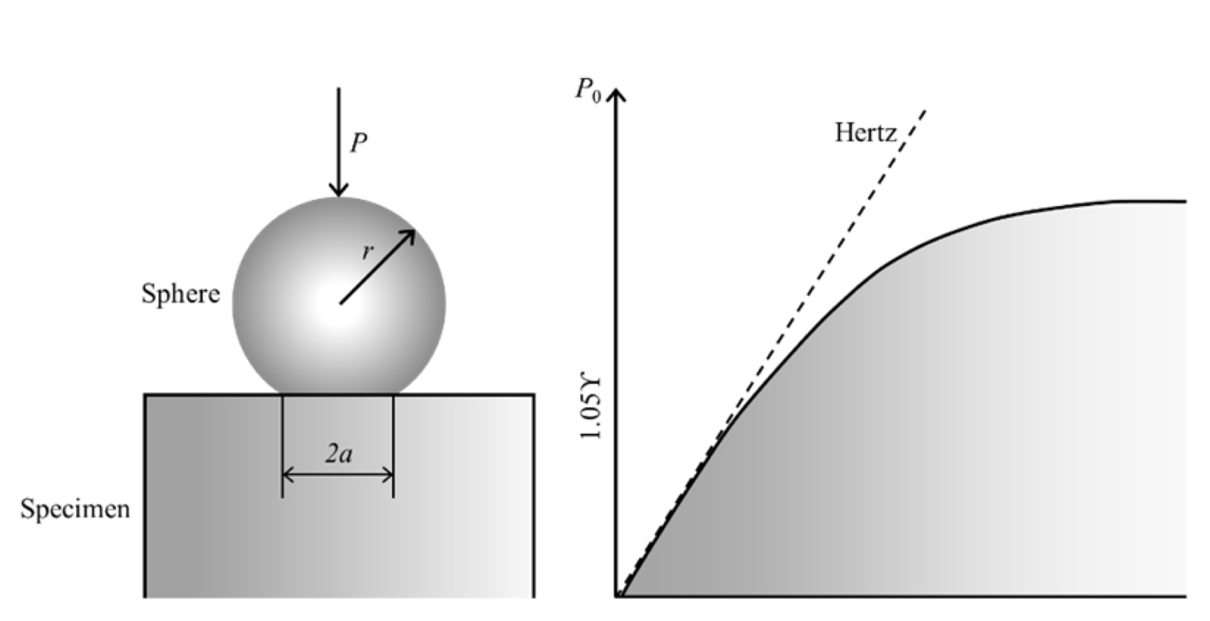
The mechanical behaviour of the sintered carbon fiber admixed Al2O3 porous ceramics were investigated using Hertzian indentations tests as shown in Fig. 3.32) The samples were shaped cylindrically in 1-inch diameter and polished finely. Hertzian indentation tests are done in air with universal testing instrument (Model 5567, Instron Corporation, Canton, MA) with keeping cross-head constant as a speed of 0.2 mm/min for a load range of P = 5 ~ 200 N, using spheres of tungsten carbide having radius of r = 6.35 mm. The load-displacement graphs were drawn while loadings and un-loadings. To convert the displacement amplifier were used. The displacements were converted through converters, amplifier and the digital signal processor consecutively after measuring with extensometer.
3. Results and Discussion
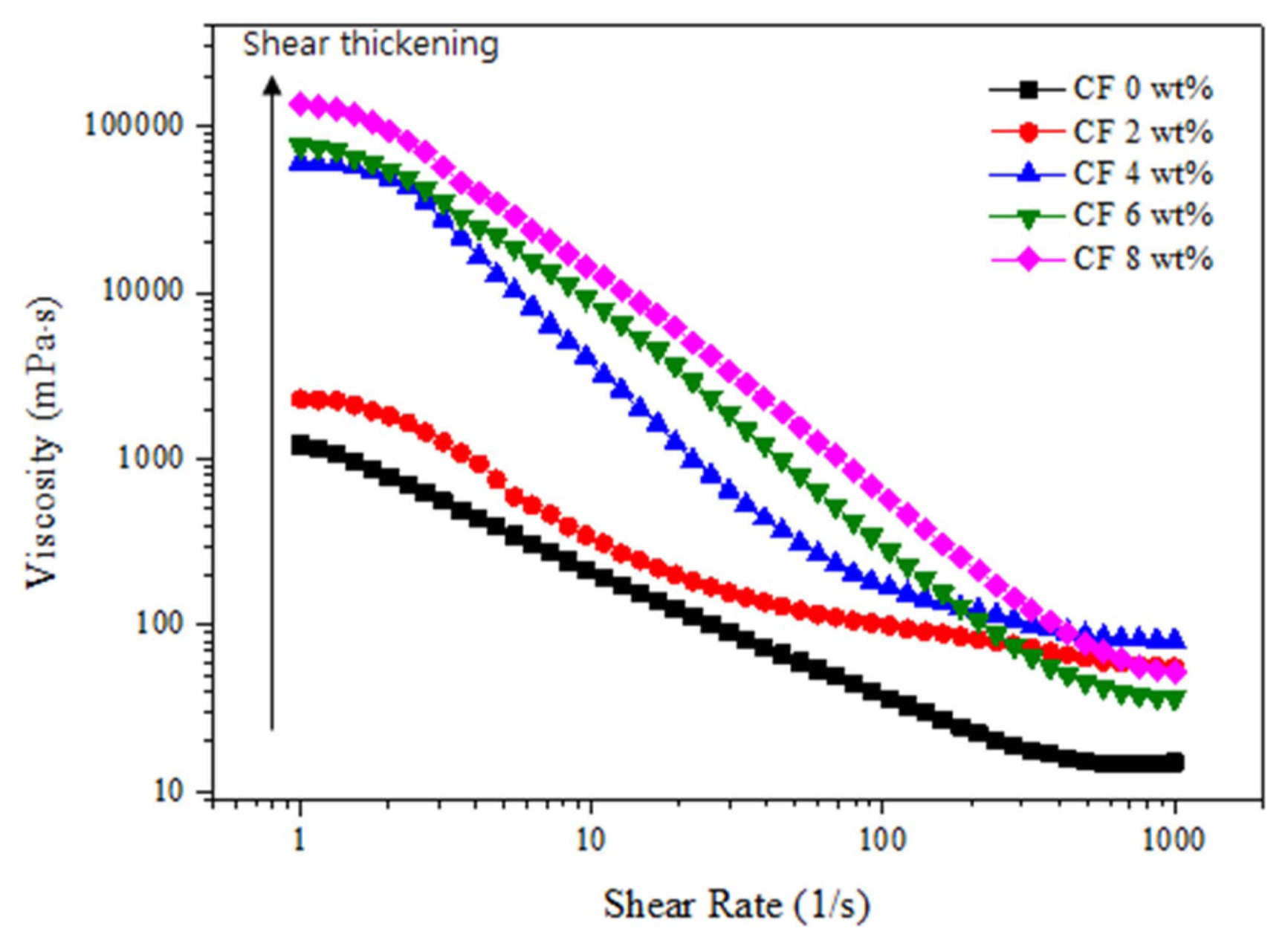
Figure 4 shows the viscosity graph of the Al2O3 slurry with different carbon fiber content. The viscosity of the Al2O3 slurry decrease while increasing the shear rate and exhibits the typical shear thinning behaviour of a non-Newtonian fluid. The viscosity of the Al2O3 slurry increased as the carbon fiber content increased up to 8 wt.%. However, the suspension without carbon fiber shows narrow range of viscosity in all ranges of shear rates, that have higher impact on the Van der Waals force which are always present there in a colloidal system,33) and the addition of a carbon fiber leads to a considerable increase in viscosity. Fig. 4 illustrates that all suspensions exhibit a typical shear-thinning behaviour with increase of shear rate. This shear thinning behaviour can be observed at lower range of shear rates where the surface forces within the particles dominate the rheological behavior.
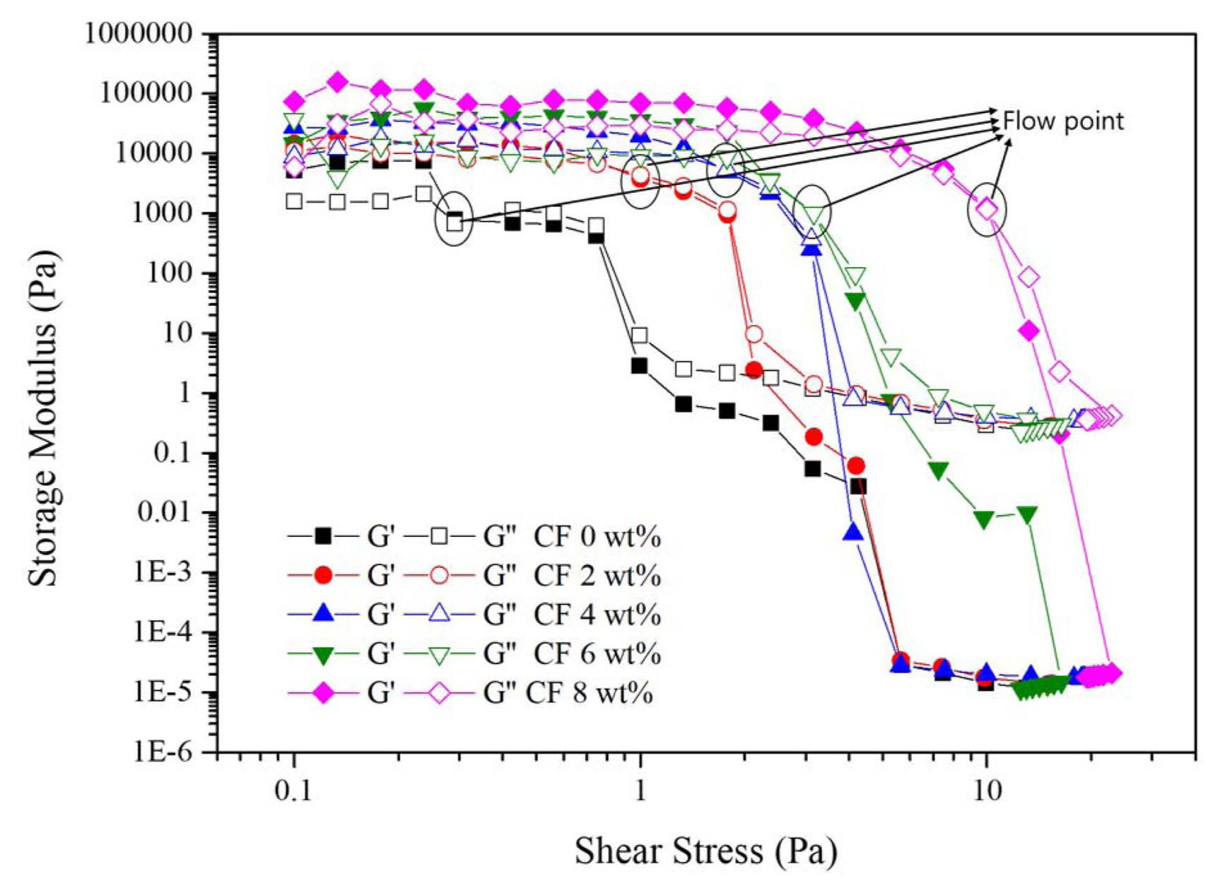
Figure 5 and Table 2 shows the amplitude sweep stress-modulus graph. The steady range where the storage modulus remains almost constant is the LVE range and the limiting value of the LVE range is the yield point. The cross point of the storage(G’) and loss modulus (G”) is called the flow point, where it finally starts to flow. The G’ values of the slurry with carbon fiber content were higher than the G” values. Over the yield stress, G’ and G” crossed over so the G’ became lower than G”, and the flow of the slurry starts. Over the yield stress, the slurry starts to flow, and the particles or the aggregation moved in the slurry. The yield point decreases with an increase in carbon fiber content, and the flow point increases as the carbon fiber content increases. The addition of carbon fiber in the slurry results in the breaking of the internal structure with a smaller shear stress. However, with the increment in the shear stress of the flow point of the slurry increases while adding the carbon fiber content up to 8 wt.%, where the viscoelastic gel structure changes to the liquid-like structure. That means the particles in the suspensions are bound more tightly.33)
Figure 6 shows study of the thixotropic effect on the recovery of the colloidal suspension as the effect of shear history and time of the suspension with the help of 3ITT (Three interval thixotropy test), which is performed mostly using the mode with controlled shear rate. The three intervals taken are different shear rat as follows, Interval 1 (shear rate 1 s−1, 15 s) followed by Interval 2 (shear rate 100 s−1 or 500 s−1, 10 s) and finally Interval 3 (shear rate 1 s−1, 60 s). In a typical condition, the interval 1 and interval 3 flow curves are found in linear scales. The graphs plotted in Interval 3 shows the amount of structure recovery obtained with in certain period of time in comparison to Interval 1. The recovery is faster when the carbon fiber content is not added and at Interval 2 at lower shear rate. The recovery is within 1 sec for pure Al2O3 slurry, the viscosity in Interval 3 increased higher than the viscosity in Interval 1 due to the dispersion of the carbon fiber at Interval 2 where higher shear rate was appliede. The slurry with 2% carbon fiber revealed a higher thixotropy than the slurry without carbon fiber, and recovery is 98% when the shear rate for interval 2 is 100 s−1, and it is 97% when the shear rate of interval 2 is 500 s−1. This higher thixotrphohy results into the wet foam with higher stability on foaming.33)
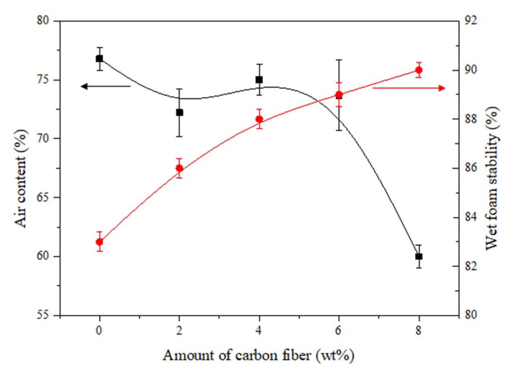
Figure 7 shows the relation between the air content and average wet foam stability of the Al2O3 suspension with respect to the different wt.% of carbon fiber content added. High volume foams with an air content of up to 78% foamed upon mechanical frothing with the maximum wet foam stability of more than 90% was obtained, which strongly indicates the stabilization of the wet foam due to the attachment of particles in the air-water interface. The wet foam stability and air content were measured, and an increase in carbon fiber content from 2 to 4 wt.% resulted decrement in the air content while the wet foam stability increased. With a further increase in carbon fiber content of 6 to 8 wt.%, the air content was controlled and wet foam stability sparingly increased to 87% and 90% respectively. The addition of the carbon fiber content up to 4 wt.% was found to be unstable and due to higher air content in the foam incorporate the higher amount of gas leading bigger sized bubbles which leads to the lower wet foam stability in comparison to the one with higher wt.% where the air content was controlled which gave higher wet foam stability.
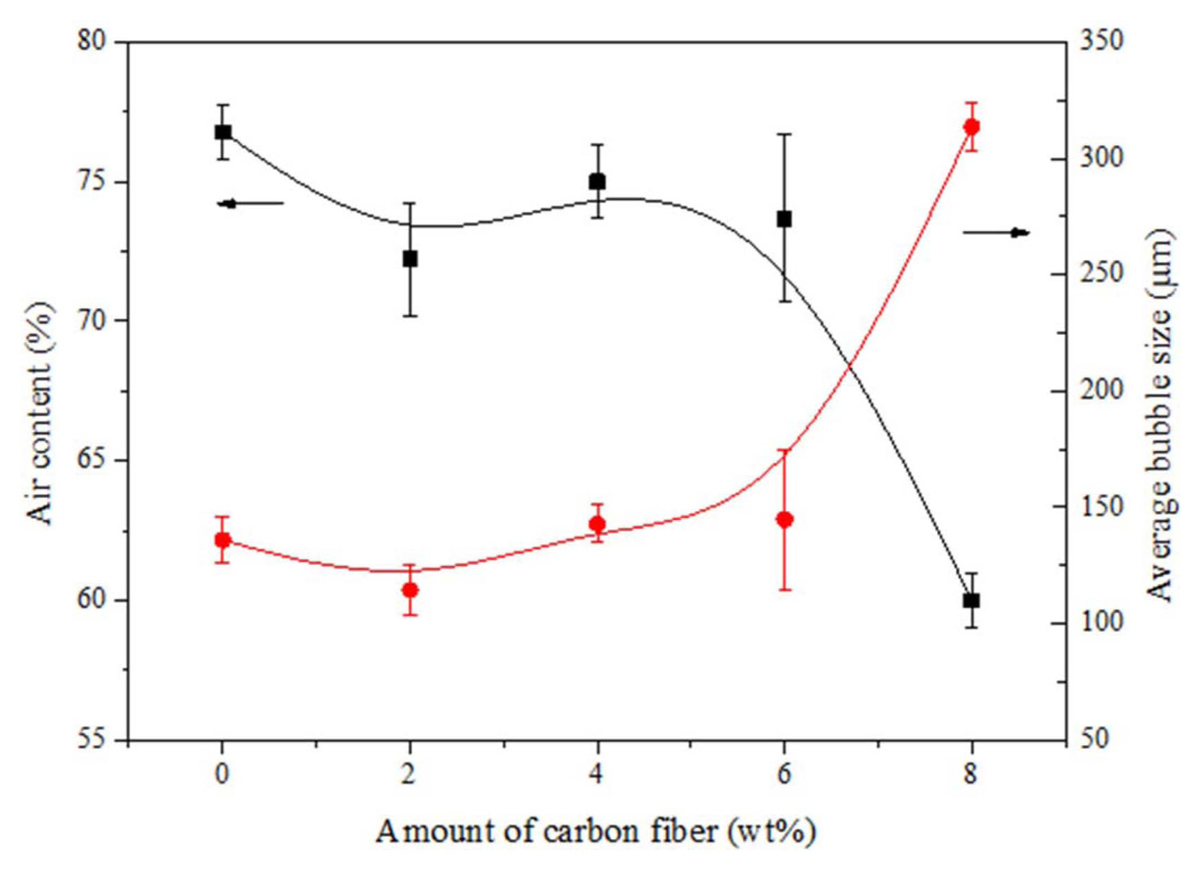
Figure 8 shows the relation between the air content and the average bubble size with respect to the increasing carbon fibre content. The result described in graph shows that the colloidal suspension without a carbon fibre content exhibits a controlled air content of 60% with a larger bubble size of 300 mm. The bubbles contained in the suspension with a higher air content cannot achieve stability as the pressure difference at the air-water interface tends to collapse the bubbles in the wet foam. With an increase in the carbon fibre content, the air content of the colloidal suspension decreases with a corresponding increase in the bubble size. The addition of the fibre content from 6 wt.%-8 wt.% results in an optimum surface with moderate bubbles sizes in the range of 150 mm maximum wet foam stability.
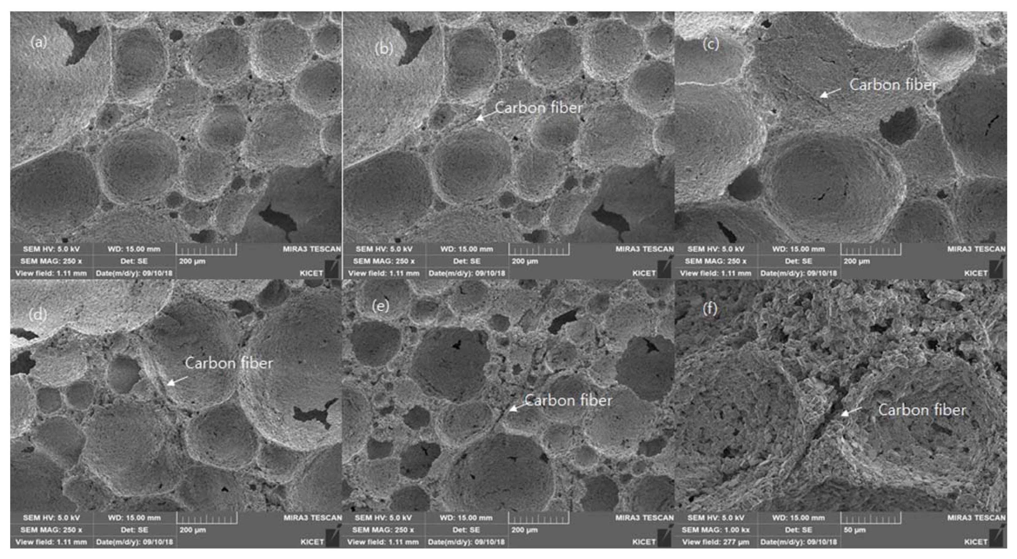
Figure 9 shows the microstructures of Al2O3 based porous ceramics with different wt.% of carbon fiber (2 wt.%: CF2, 4 wt%: CF4, 6 wt%: CF6, 8 wt%: CF8) porous ceramics which were sintered at 1500°C for 1 h. The microstructures that were obtained generally consist of closed inter-connected pores with a narrow size distribution of the Al2O3. The porous ceramics with the carbon fiber content was found supportive to overcome the destabilization mechanism like Ostwald ripening are minimized as the smaller bubbles are controlled to get diffused into lagrge bubbles as the strands of the carbon fiber lies in between two bubbles which checks the bubble to get diffused and results to give higher foam stability to high volume of porous ceramics. As it can be observed in Table 2 the mechanical properties of the porous ceramics which can be attributed to the fact that the carbon fiber added to to colloidal suspension bounds the foams and make it more stable and the higher amount of the carbon fiber gives more hindrance to the strength of the porous ceramics.
Figure 10 shows the indentation load-displacement curves for the Al2O3 with different weight percent of the carbon fibre (2 wt%: CF2, 4 wt%: CF4, 6 wt%: CF6, 8 wt%: CF8) sintered at 1500°C for 1 h, which is a plot between compression (indentation) load P against compression strain (displacement) (d) using WC ball with a radius of r = 6.35 μm. The curve for the Al2O3 with CF0 and CF2 are found considerably lower and flatter than that for the higher wt.%, indicating a much quasi-plastic material. This indicates a “high damage tolerance” of the specimens under constrained spherical indentation. Whereas, for the 8 wt.% can be noted to have the highest porosity of about 65.07% (from Table 2), which infers the highest compressive load with respect to the displacement.
Table 3 shows the detail information of the sintered Al2O3 porous ceramics where carbon fiber was added as a foam agent before foaming to improve the physical and mechanical properties of porous ceramics. While having a look at density of the porous ceramics with no carbon fiber was found to have lowest value of 0.270 g/cm3 while the one with 8 wt.% carbon fiber content was found highest density of 0.450 g/cm3 which is nearly double. The another parameter taken is related to the pores of the ceramics thus formed in case of pore size of Al2O3 porous was found little high but on adding the carbon content the pore size of 320 μm with porosity of 58.35% but it was gradually increased with the increment of the carbon fiber content and the pore size and porosity was found maximum with the higher carbon fiber content of 8 wt.% with pore size of 0.450 (g/cm3 and porosity of 65.07% pore size and pore structure can be seen in Fig. 9 which was due to the removal of the carbon fiber content by redox reaction during the sintering process.
After discussing about physical properties, the mechanical properties are discussed. The mechanical properties are found to be improved with addition of carbon fiber. The elastic modulus in case of Al2O3 was found 30.61 MPa while the one with the 8 wt.% of carbon fiber content 57.44 MPa which was gradual improvement with the carbon fiber content of 8 wt.%. The compressive loading & displacement was also found improved while adding the carbon content where the compressive load value observed with a sample with no carbon fiber content was found 112.49N which then decreased in adding 2 wt.% carbon fiber content which then was improved gradually which then was found highest with 8 wt.% with the compressive loading value of 156.48N which was nearly 150% the pure Al2O3 porous ceramics.
4. Conclusions
This study focused on the wet foam stabilization of the colloidal suspension and mechanical properties of porous alumina based porous ceramics. The wet foam stability of more than 90% was obtained with 8 wt.% of the carbon fiber content with a controlled air content. The bubble size of the wet foam was found to me minimum of 120 mm with the Al2O3 porous ceramics without carbon fiber while it was increased upto 350 mm with the carbon content of 8 wt.%. generally bigger bubbles get collapsed but in this case the bubbles were preserved by the carbon fibers which was placed in the inter-bubble space which prevent on further growing of the bubble and this attributed to the higher wet foam stability. Corresponding to this the porous ceramics thus prepared was found with higher pore size of 380 mm with 8 wt.% of the carbon fiber while it was just 320 mm without carbon fiber with the porosity increased from 58.35% without carbon fiber to 65.07% with 8 wt.% of carbon fiber content. Following to this the mechanical properties was found to be improved with the improvement in elastic modulus from 30.61 MPa to 57.44 MPa and compressive load of 112.49 N to 156.48 N with 0. wt% of the carbon content to 8 wt.% of the carbon fiber content. With this analysis it can be conformed that the carbon fiber content have positive influence in the colloidal and mechanical properties of the porous ceramics.