1. Introduction
Silicon carbide (SiC) is an attractive high temperature structural material owing to its excellent mechanical, thermal, and chemical properties.1-4) In addition, the high resistance under neutron irradiation makes SiC as a best candidate for the structural component of nuclear reactors.5) Because a monolithic SiC shows an inherent brittleness, however, SiC fiber-reinforced SiC composite (SiCf/SiC) has attracted considerable attention to alleviate the brittleness under a mechanical load.6-11)
For many practical applications, SiCf/SiC needs to be fabricated to large size with complex shape, which is difficult to prepare using a simple hot press technique. Therefore, the development of an adequate joining technology is essential to broaden its applications. Several methods developed so far include the solid-state diffusion bonding,12,13) glass-ceramic bonding,14,15) transient eutectic phase joining,14) Si-C reaction bonding,16,17) and MAX phase joining.18-20) Most studies used SiC monolith as a joining body, while the joining of SiCf/SiC is more difficult than the joining of SiC monolith. For example, Singh reported the joining of SiC monolith by infiltrating molten silicon and achieved a flexural strength up to 255 MPa.21) However, Lewinsohn et al. joined SiCf/SiC composites using the same method and obtained a moderate flexural strength of 78 MPa.17) Nevertheless, joining strengths higher than 100 MPa are generally needed for practical applications.22) Accordingly, further study to obtain higher SiCf/SiC joining strengths is needed.
With this background, the joining of SiCf/SiC was performed using 2 types of MAX phases, such as Ti3AlC2 and Ti3SiC2, because both phases show good mechanical properties as well as high resistance under neutron irradiation.23-28) Both Ti3AlC2 and Ti3SiC2 are expected to be good filler materials for the joining of SiCf/SiC by solid-state diffusion owing to their easy decomposition in the presence of SiC at high temperatures.29,30) To the best of the authors’ knowledge, there are no reports on the joining of SiC-based materials using Ti3AlC2, although the joining using Ti3SiC2 MAX phase only for monolithic SiC has been reported.18-20)
2. Experimental Procedure
The SiCf/SiC joining body was fabricated by the electrophoretic infiltration of a matrix slurry, containing SiC and 12 wt.% Al2O3-Y2O3 sintering additive, into a 2 dimensionally-woven SiC fabric (TyrannoTM-SA grade-3, Ube Industries Ltd., Japan) preform. The SiC fabrics were coated with a 400 nm-thick PyC layer through the decomposition of CH4 at 1100°C. Fifteen layers of infiltrated SiC fabrics were stacked after inserting the SiC green tapes alternatingly, which have the same composition with the matrix slurry. Hot pressing was performed at 1750°C and 20 MPa for 2 h in an Ar atmosphere. The resulting SiCf/SiC with a dimension of 200 × 200 × 3 mm3 showed 94% density, which was cut to 30 × 15 × 3 mm3 for the further joining test. The experimental setup and detailed procedures for SiCf/SiC fabrication can be found elsewhere.31-33) Ti3AlC2 and Ti3SiC2 (both purchased from Beijing Jinhezni Materials Co., Ltd., China) with a purity ≥ 98% and a mean particle size of 32 and 21 μm, respectively, were used as the filler materials by casting into a 60 μm-thick green tape.
After polishing the SiCf/SiC surface to a 1 μm diamond paste, the filler tape was inserted between two SiCf/SiC bodies to have a butt-joint configuration.18) The joining sample was placed in a graphite mold after spraying BN powder for easy sample separation from the mold followed by the binder burn-out at 350°C for 2 h in air at a heating rate of 0.5°C/min. Subsequently, joining was performed at 1600 or 1750°C for 1 h under a pressure of 3.5 MPa in an Ar atmosphere using a hot press. The density after joining was calculated by Archimedes’ method and compared to that of the samples before joining.
Joined sample was cut into 4 bars having a dimension of 30 × 4 × 3 mm3 using a diamond saw followed by polishing to a 1 μm diamond paste. For the 4-point bending test, a universal testing machine (UTM AG-50E, Shimadzu, Japan) was used with a load speed of 0.5 mm/min. The following equation was used to calculate the flexural strength:
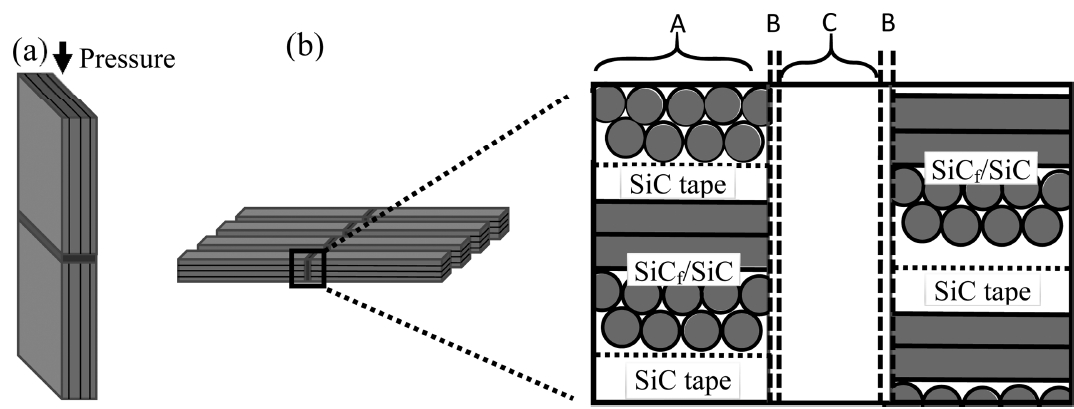
where σ is the flexural strength (MPa), P is the applied load (N), a is the width (mm), b is the thickness (mm), L1 is the inner span (mm), and L2 is the outer span (mm). Three samples for each condition were tested at room temperature. The fractured surfaces were analyzed by a X-ray diffractometer (XRD, X’Pert-PRO MPD, Pan Analytical with 40 kV and 30 mA) using Cu Kα radiation (λ = 0.154 nm) to check the phase generation and transition upon joining along with the morphological analysis by scanning electron microscopy (SEM, Hitachi S-4800, Japan). One remaining sample was used for microstructural and elemental analyses by SEM equipped with energy dispersive X-ray spectrometry (EDS, Horiba EX-250, Japan). The schematic of joining configuration for the sample is shown in Fig. 1.
3. Results and Discussion
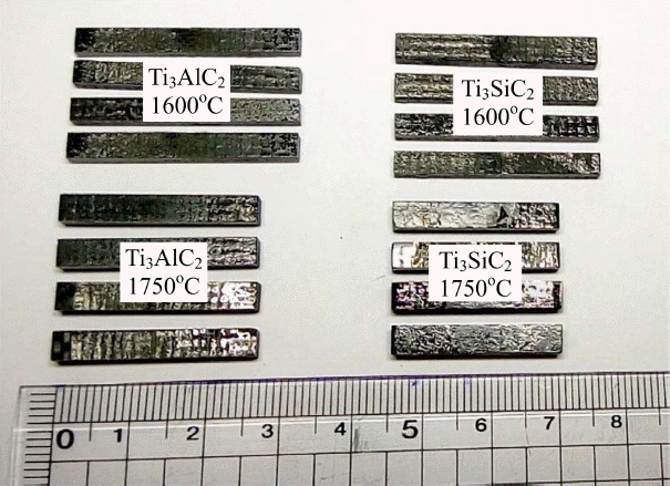
From a practical point of view, joining under low pressure or pressureless conditions is desirable as far as sufficient joining strength is ensured. Therefore, a low joining pressure of 3.5 MPa was used because pressureless joining revealed a weak joint based on a preliminary test. No noticeable changes in dimensions were observed after joining at 1600°C, while approximately 10% reduction of the sample to the direction of the applied pressure was observed at 1750°C, as shown in Fig. 2. The shrinkage upon joining at 1750°C resulted from the further densification of SiCf/SiC; the density of SiCf/SiC before and after joining at 1600°C was similar to 94% approximately, whereas that after joining at 1750°C increased to 98%.
Table 1 lists the flexural strength of the SiCf/SiC samples joined in this study using different fillers and joining conditions, while the previously reported values for a SiC monolith joint using Ti3SiC2 powder or tape are also shown for comparison.18-20) The joining strength of SiCf/SiC increased with increasing joining temperature, i.e., 100 to 161 MPa using Ti3AlC2 and 92 to 178 MPa using Ti3SiC2 after joining at 1600 and 1750°C, respectively. Compared to the values reported for monolithic SiC joints using Ti3SiC2 tape or powder, this study revealed a comparable or even higher joining strength despite SiCf/SiC was used as the joining body. Considering the lower pressure of 3.5 MPa in the present study than those of previous studies (20 - 50 MPa), temperature is believed to be a more important factor for the joining strength than the applied pressure.
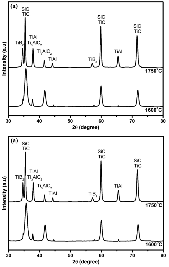
Figure 3(a) and (b) present XRD patterns of the fractured surface of SiCf/SiC joint using a Ti3AlC2 or Ti3SiC2 filler, respectively, at two different temperatures. TiAl and TiSi2 intermetallic compounds for the Ti3AlC2 and Ti3SiC2 fillers, respectively, were detected in the fractured surface, indicating the corresponding phase generation during the joining process. Relative peak height of the intermetallic compounds was increased along with the decrease in MAX phase peak height in Fig. 3, suggesting the intermetallic compounds were formed by the decomposition of MAX phase.
According to previous report on the high temperature stability of Ti3AlC2 MAX phase, Ti3AlC2 can easily decompose to TiC and Ti2AlC at 1400°C by the following reaction:34)
However, Ti2AlC was not detected in the fractured surface because Ti2AlC is not a stable compound above 1400°C,35) thus further decomposition of Ti2AlC to Ti, Al, and TiC might be occurred by the following reaction:
Because Ti and Al are very reactive elements at high temperatures, they can react each other to form TiAl intermetallic compound, where the Gibbs formation free energy is highly negative, i.e., −46.58 and −42.5 kJ/mol at 1600°C and 1750°C, respectively. This exothermic reaction for the formation of TiAl may enhance the solid-state diffusion for the joining, providing a good bonding.36) The presence of TiB2 compound in Fig. 3(a) can be explained by the reaction between Ti from Ti3AlC2 and B from BN spray, as shown with the following reaction:37)
where TiN can be transformed further to TiB2 in the presence of BN by the following reaction:38)
Because the reaction (4) and (5) are very spontaneous at > 1500°C based on their highly negative Gibbs formation free energy, TiN was not detected in the final product. During the joining at 1600 or 1750°C, however, some metals and intermetallic compounds might be participated as liquid phase for the above reactions because of their relative low melting point (Tm), including, Ti (Tm = 1668°C), Al (Tm = 660°C), TiAl (Tm = 1460°C), and Ti2AlC (Tm = 1625°C).
Similarly, Ti3SiC2 may decompose into TiCx and Si by the selective outward diffusion of Si at temperature > 1400°C, according to the following reaction:29)
Furthermore, the formation of Si (Tm = 1414°C) can enhance the decomposition of Ti3SiC2 by forming TiSi2 (Tm = 1470°C) and SiC, based on the following reaction:39)
According to the reaction equations (2), (3) and (6), the decomposition of both Ti3AlC2 and Ti3SiC2 resulted in the formation of TiC as a final product. Even though the TiC peaks in Fig. 3 are elusive because the TiC peak positions coincide with those for SiC, the presence of TiC was confirmed further by the SEM and EDS results, as shown in Fig. 4 and Table 2, respectively.
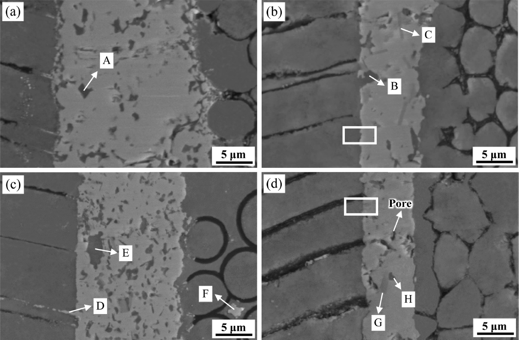
Figure 4 presents SEM images of the SiCf/SiC joining region using a Ti3AlC2 or Ti3SiC2 MAX phase after joining at 1600 and 1750°C for 1 h, where the joining region could be identified from the SiCf/SiC body by different contrast. All showed a sound joining morphology without the formation of cracks at the interface as well as joining region. However, a few small pores are found after joining using Ti3SiC2 at 1750°C, as shown in Fig. 4(d), owing to the decomposition of MAX phase.40,41) On the other hand, the absence of pores in case of using Ti3AlC2 filler might be attributed to the formation of TiAl metallic compound, which could fill the pores due to its inherent ductility. One notable thing in Fig. 4 is the deformation of the initial round-shaped SiC fiber into the polygonal shape upon the joining at 1750°C, while the original round shape was maintained after joining at 1600°C. The deformation of SiC fibers during the initial hot pressing at 1750°C, 20 MPa for 2 h was not significant, while a polygonal-shaped fibers are observed after joining at 1750°C, 3.5 MPa for 1 h, as shown in Fig. 4(b) and (d). This enhanced deformation of SiC fibers at 1750°C during joining might be attributed to the longer exposure at high temperature or concentrated pressure effect, which was applied to the parallel direction to the fiber. On the other hand, the pressure was applied to the perpendicular direction to the woven fabric during initial hot pressing using a large size of 200 × 200 × 3 mm3 SiCf/SiC, in which the fibers can sustain against the external pressure. The deformation of the microstructure by the combined effects of longer exposure at high temperature and pressure applied to the parallel direction to the fibers can explain the shrinking of the sample and increase in the density after joining at 1750°C, as explained above. The other notable thing in Fig. 4 is the significant decrease in filler thickness from its initial 60 μm-thick tape, which decreases further by increasing the joining temperature from 1600 to 1750°C. The degree of reduction in tape thickness was slightly higher with Ti3SiC2 than Ti3AlC2, where both tape thickness decreased less than 10 μm after joining at 1750°C from the initial 60 μm, showing a linear shrinkage higher than 80%. Because this shrinkage rate exceeded the typical linear shrinkage of the green tape around 30% after the high temperature treatment, this implies the decomposition of both MAX phases followed by the solid-state diffusion of filler elements into the SiCf/SiC body.
Table 2 lists the results of EDS elemental analysis for the points marked in Fig. 4. According to the results, the dark phases marked with “A” and “B” in the joining region using Ti3AlC2 filler revealed the presence of approximately 27 at.% Si. Because Ti3AlC2 does not contain Si, this indicates the inward solid-state diffusion of Si from the SiCf/SiC bodies into the Ti3AlC2 joining region. Moreover, a small needle-shaped phase with different contrast, pointed by the letter “C” in Fig. 4(b), is TiAl intermetallic compound based on its 48% Al and 52% Ti composition, which agrees to the XRD results shown in Fig. 3(a).
The migration of bright Ti3AlC2 and Ti3SiC2 filler phases along the voids in SiCf/SiC at the joining interface can be observed in Fig. 4(a) and (c), especially marked with “D” in Fig. 4(c). This is due to the high temperature plasticity of Ti3AlC2 and Ti3SiC2 MAX phases at above 1200°C under a pressure,42,43) which can improve the joining property by eliminating pores and bridging the filler and body. There are many small dark phases in the joining region when the Ti3SiC2 tape was used as a filler, as shown in Fig. 4(c). These are estimated as SiC, which was formed by the decomposition of Ti3SiC2, according to the reaction (7). However, the bright phase marked with “F” in the SiCf/SiC region is the segregated liquid-phase Al2O3-Y2O3 sintering additive, based on its compositional analysis shown in Table 2. In addition, the phase marked with “G” in Fig. 4(d) with slightly different contrast is confirmed as TiC phase, based on its atomic composition in Table 2.
The joining mechanism using Ti3AlC2 and Ti3SiC2 filler is based on the decomposition of MAX phases followed by solid-state diffusion and high temperature plasticity, as explained above. However, the degree of decomposition of MAX phase is reported to be affected by atmosphere, where the presence of SiC seems to be very important for easy decomposition. For example, Bentzel et al.29) found more enhanced decomposition of Ti3AlC2, and Dong et al.19) detected faster decomposition of Ti3SiC2 in the presence of SiC than the absence of SiC at ≥ 1300°C. Therefore, the decomposition of MAX phases seemed to be triggered at the joining interface,19,20) which has a Si-rich environment owing to the contact with SiCf/SiC. According to the literatures, Ti3AlC2 transforms easily to Ti3Al(Si)C2 upon the inward diffusion of Si ions because of the smaller Si ionic size than Al along with the low Al vacancy formation energy in Ti3AlC2.44-46) Furthermore, Ti3SiC2 and Ti3Al(Si)C2 can decompose into TiC upon the loss of Al and Si, where the decomposition of Ti3AlC2 and Ti3SiC2 to TiC is reported to be enhanced in C-rich environment due to its poor carburization resistance.29,47)
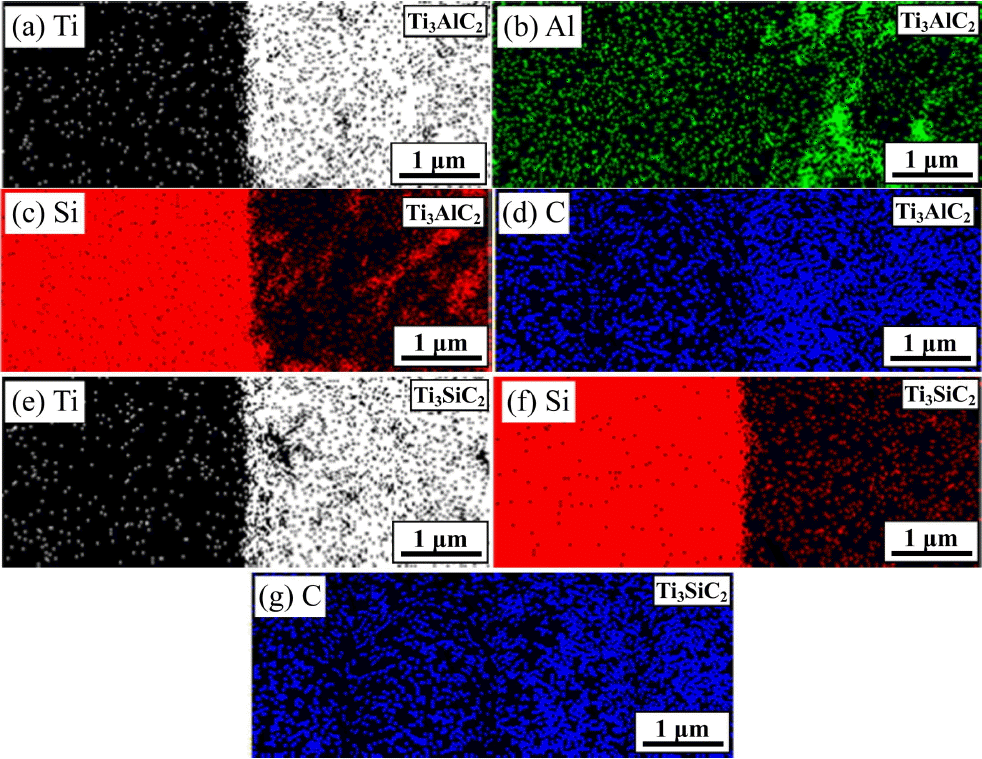
To verify the elemental diffusion upon the joining of SiCf/SiC using Ti3AlC2 and Ti3SiC2 filler, Fig. 5 presents the EDS elemental mapping results at the joining region for the area shown with rectagle in Fig. 4(b) and (d), respectively, revealing the distribution of Ti, Al, Si and C element. It shows that Al has the highest degree of diffusion due to its high vapor pressure and low bonding strength, while Ti reveals the lowest degree of diffusion due to the strong covalent bonding with C in Ti3AlC2 along with larger ionic size, as shown in Fig. 5(a) - (d). Moreover, Fig. 5(c) shows the presence of Si in the Ti3AlC2 filler region, indicating the solid-state diffusion of Si from the SiCf/SiC bodies. Because the MAX phase has a layered structure of two adjacent Ti-C-Ti-C-Ti (TiC0.67) covalent bonding chain, where Al or Si ions intercalated in between the layers, the Al or Si can diffuse easily into the MAX phases.48,49) The distribution of Ti, Si and C elements in the Ti3SiC2 joining region shown in Fig. 5(e) - (g) is similar to that of Ti3AlC2. This temperature-dependent ionic diffusion confers the high joining strength to the SiCf/SiC joining, which increases with the increase in temperature owing to the enhanced solid-state diffusion. However, the significant increase in the joining strength by increasing the temperature from 1600°C to 1750°C, as shown in Table 1, may not only be attributed to the solid-state diffusion but also be affected by the liquid-phase Al2O3-Y2O3 sintering additive in the SiCf/SiC bodies. It is believed that the liquid phase at the joining interface plays a crucial role in promoting the bonding by offering a rapid diffusion path for atomic migration.50)
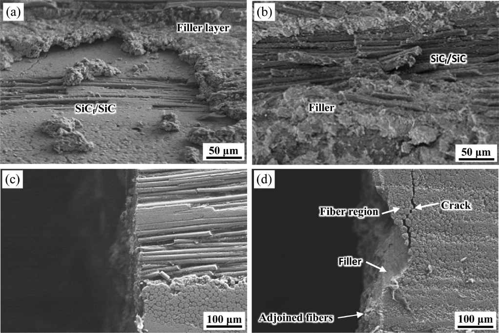
Figure 6 shows the typical fractured surface of the SiCf/SiC samples joined using Ti3AlC2 at 1600 and 1750°C. The top-view image for the fractured surface joined at 1600°C in Fig. 6(a) reveals a relatively smooth surface, showing the bare SiCf/SiC body owing to the fracturing along the joining interface. On the other hand, the fractured surface joined at 1750°C in Fig. 6(b) shows rough surface because of the strong attachment of Ti3AlC2 filler onto the SiCf/SiC body. The side-view image for the sample joined at 1600°C in Fig. 6(c) shows a flat surface, while that joined at 1750°C shows rough surface along with the presence of adjoined SiC fibers. Therefore, the joining of SiCf/SiC using Ti3AlC2 filler at 1600°C is desirable to minimize the damage on the SiC fibers, while the joining should be performed at 1750°C to obtain higher joining strength although the deformation of the SiCf/SiC body needs to be minimized by increasing the density before joining in this case. However, further experiments are needed to find an optimal condition which ensures the requirements for practical applications.
4. Conclusions
The joining of SiCf/SiC composites was performed using a Ti3AlC2 or Ti3SiC2 MAX phase tape at 1600 or 1750°C under 3.5 MPa pressure using a hot press. The joining flexural strength for a butt-joint SiCf/SiC increased with increasing the joining temperature, i.e., 100 to 161 MPa for Ti3AlC2 and 92 to 178 MPa for Ti3SiC2 filler after joining at 1600 and 1750°C, respectively. This high joining strength was explained by the elemental diffusion upon the decomposition and high temperature plasticity of the MAX phases along with the effects of Al2O3-Y2O3 liquid phase sintering additive added to the SiCf/SiC joining body. To explain the decomposition mechanism of Ti3AlC2 and Ti3SiC2 MAX phases, the phases generated during the high temperature treatment were confirmed using XRD and EDS mapping results along with the possible reaction equations. The significant decrease in the filler tape thickness upon joining supported the decomposition of the MAX phases, which was enhanced by the presence of SiC. Even though the deformation of SiCf/SiC was observed for the joining at 1750°C, the joining at this temperature was suggested owing to the significant improvement in joining strength up to 178 MPa and strong interfacial bonding showing a fracturing through the SiCf/SiC joining bodies rather than the interface.


